
I bought my first house at the start of the COVID-19 pandemic. Having been built in the early 70’s, it was going to need a lot of work to bring it up-to-date, including a full rewire. All of the walls were going to be re-plastered and the floors taken up, so I knew I had a golden chance to add in any cable runs I could think of for future provision. Network cabling was the first thing that crossed my mind, so I went about planning that out. Somewhere along the way of researching equipment for my future home computer network, I stumbled across some home automation articles/videos. I subsequently had the brain wave that it would be pretty cool to be able to control the lighting in the house remotely, but utilising wired links as much as possible. This wouldn’t have been something I would have considered at all if the renovation in my house was already complete, but given the fact that I had the chance to put whatever cabling I wanted into the walls, I decided it was a good opportunity for a bit of a lockdown project.
I was well aware of the plethora of smart home devices available; however I had always been a bit put off. I saw the smart home world as a bit of a gimmick, primarily because there are an awful lot of cheap, gimmicky devices on the market. In my opinion, something as basic as the lighting in your house has to be 100% reliable. You don’t want to walk into a room, flick the light switch and have to worry about whether the lights will decide to come on or not. That, to me, is a completely unacceptable situation, but one that many people who have taken a foray into the world of smart lighting have unfortunately probably encountered.
Being a hardware design engineer and an avid hobbyist/maker, of course I quickly came to the resolution that I was going to design my own system, blissfully unaware of the magnitude of the project that was forming in front to me. I design aerospace data acquisition systems for a living, so reliability is well drilled into me (in case you haven’t gathered from the above rant!). I felt I was going to be able to make a fairly decent attempt at devising a system that would work for me.
As any hobbyist will understand, a huge part of the motivation for undertaking a project like this is the joy of executing the project itself. Coming up with a list of requirements, converting those requirements into a design concept, refining the design into something that will (hopefully) perform the required task and, of course, testing it once it’s built. This may seem like a crazy thing to do with your spare time to someone who doesn’t have the interest, but to someone like me, the above is actually quite fun!
My hope from documenting this project is that somebody may find some inspiration from it, may have some feedback or suggestions for me or, if nothing else, may just find it an interesting read.
I will highlight at this point that undertaking this project required working with mains electricity which, of course can be extremely dangerous. I am not an electrician, but I am well able to work safely. If you want to copy anything you see in this project and are not comfortable and experienced at safely working with mains wiring, then please do not attempt it. There are many ways that what follows could be adapted to use off-the-shelf smart lighting products, meaning you don’t have to venture outside of the safety of coding and low voltage electronics.
Initial Design Choices
I had fairly quickly created a rough list of hardware design requirements mentally, but I had to make sure that the project as a whole was going to be viable before spending lots of time selecting components and designing PCBs. With regard to the software side of things, I wasn’t too sure… I knew for certain that I wasn’t going to be designing my own smartphone app anyway, so I was going to have to piggyback on an existing system. I wasn’t fussy about the UI I was going to go with. There are plenty of internet debates about which “smart assistant” is the best, most of which will not provide any help to someone trying to decide on which is best for them. In the end, I decided it made most sense for me to go with Apple Home. Both myself and my girlfriend have iPhones, so this would be nicely integrated into our devices already. The only problem I had was, how I was going to interface my custom hardware with it.
When scoping out the requirements of a project like this, there will always be plenty of unknowns to begin with. I always try to first see if it’s possible to find a path from the unknowns back to a domain that you are comfortable with. In this case, the unknown was how to access the “under the hood” information within Apple Home. If I could find an interface that would be able to communicate that back to something like a python script, then the rest would be a doddle… well not quite a doddle, but I’d at least know what I was doing.
The ray of light for me was when I found some YouTube videos discussing a platform called Homebridge. This seemed quite hopeful to me as it appeared that this was going to make it possible to add my own custom accessories to the Apple Home world and the status of these virtual accessories could be reflected by a value stored in a file. Once the status information you care about is in a file, it’s easy to pick up using simple programming. Homebridge will also run on a Raspberry Pi, which is absolutely ideal – plenty of hardware I/O options here.
So that was it: I could use Apple Home/Siri as a nice, slick “control panel” for my smart home and then use Homebridge to interface this back to a python script which would, in turn, talk to the external hardware. Simple…
Note that there is a lot of hardware design detail in the following sections. If that’s not your cup of tea and you’re more interested in how I integrated Homebridge into my setup, the software details are towards the end of this blog post.
Now that I had determined that the project was viable, I went about formalising the list of hardware requirements:
- First and foremost, the system must be reliable, utilising wired connections as much as possible.
- There must be redundancy built in. Having smart control of everything is all well and good but you do not want to be at the mercy of it. In the event of the smart system going down, you don’t want to be stuck sitting in the dark, so there should be a minimum of one light per room which can be operated manually.
- It should be possible to control simple switched lights and also dimmers
- It should be possible to easily connect extra peripheral devices (like temperature sensors, motion sensors etc.)
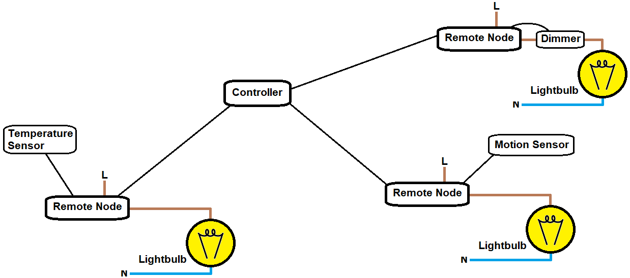
So, with the above in mind, the general concept that I came up with was a central controller which will master remote nodes around the house. The controller will be comprised of a Raspberry Pi with a few i2c port expanders hanging off it. These port expanders will be used to generate the discrete signals for driving the relays in the remote nodes and will also be able to monitor the power output status of the remote nodes. The remote nodes will be dumb i.e. not be running any firmware. That means any updates will only have to be applied to the controller. There will also need to be some sort of data connection between the controller and the remote nodes so that the temperature sensors etc. can be connected up.
In the following sections I’ll go through the hardware design of each component in more detail.
Remote Node Design
Switching
This was the first part of the system that I designed. Starting from the most basic function that this device was going to carry out: the actual switching, I decided I was going to go with SPDT latching relays. I wanted to use latching relays as 1) they don’t require any power once they have switched and 2) because of this, they will remain in whatever position they are left in if the smart system is powered down. The reason I needed to use SPDT…. that’s this type of switch by the way, in case you’re wondering:
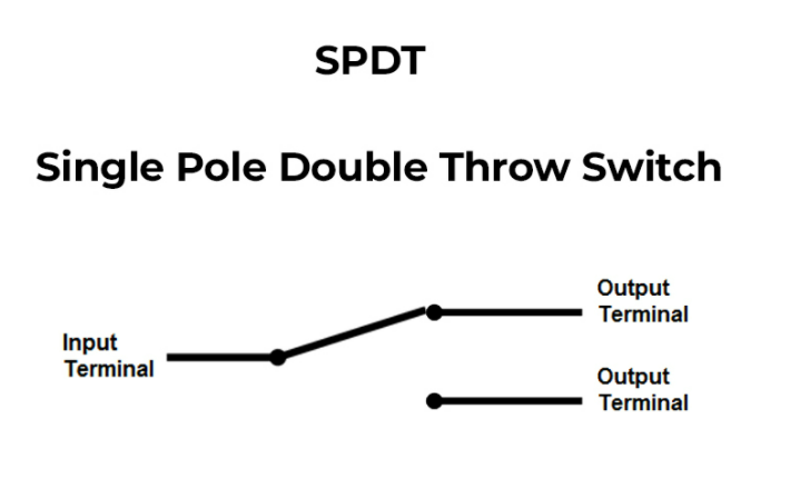
(every single time I use a switch in a design, I have to google to remind myself which one is which!)
… so anyway, the reason I needed to use SPDT is because I planned to use a dual switch design where both switches are capable of turning on and off the light they are controlling. You may be familiar with this type of operation if you have a light switch at the top and the bottom of the stairs in your house and they both control the same light. The wiring used for this switching setup is quite simple:
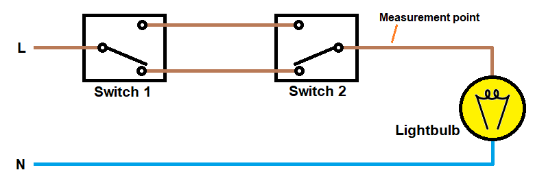
In the above the diagram, switch 1 could be a standard wall switch, so that you can manually operate the light as normal and switch 2 could be a relay which is under smart control, so therefore you get the best of both worlds. The only catch is you also need to monitor the status of the output from switch 2 (measurement point indicated in the above diagram) so that the smart controller will know if the light is currently on or off (the smart controller is aware of the current state of switch 2 (the relay), but the state of switch 1 (the wall switch) is unknown, so it would otherwise be impossible to figure out the current state of the light).
Status Monitoring
The circuit that I came up with for converting 230V AC to a logic level voltage is as follows:
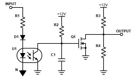
The summary of what this circuit does:
Outputs a logic level ‘1’ when mains voltage is present at the input, outputs a ‘0’ when it is not.
The details:
U1 is an opto-isolator and ensures that the mains and the controller remain isolated from one another, which is extremely important for safety and avoidance of ground loops. When there is a mains voltage present between the input and N, current will flow through the LED in the opto-isolator on the positive portions of the waveform. Using half-wave rectification like this is fairly crude, but it will do the job. R1 is quite a high value (I think I used 220k) and ensures that the LED current is kept at a reasonable level (approximately 1.5mA max, however the average will be a lot lower). The reason D1 is required is because the LED will not be able to withstand the large negative voltage that would be across the circuit during the negative portion of the waveform. The diode I used for D1 had a max reverse voltage of 400V.
As half-wave rectification is used, the photo-transistor in the opto-isolator will be pulsed on and off when there is mains voltage present at the input. C1 is used to smooth out this output. The end goal is basically to turn off transistor Q1 when there is mains detected at the input and turn it on when there’s not. Without C1, the circuit would work as intended when no mains was detected, however Q1 (and therefore the output) would pulse on and off at 50Hz when mains was present. I wanted this circuit to give a simple binary status which could be interpreted as a digital ‘0’ or ‘1’ by the downstream circuitry, so this pulsed output would not have been great. With C1 in place, it holds Q1 off when there is mains detected, even though the opto-isolator will be pulsing, resulting in a clean output. The only downside to this is the response time of the circuit when the mains at the input turns off is of the order of 100 milliseconds with the C1 and R2 values I found worked best: 10uF and 100k. I figured this trade-off was acceptable.
The ratio of R3 and R4 defines the logic level ‘1’ voltage at the output. You could leave R4 unpopulated and a ‘1’ would be represented by 12v at the output. I was aiming for 3v3 (my planned operating voltage for the downstream digital logic), so R3 is 8k87 and R4 is 3k3.
Cable Pinout
Ok, so a lot of the decisions had been made for the design of the basic switching part of the remote node. At this point, I started working on a standardised pinout for the cable runs that would go from controller to each of the remote nodes. The relays I selected (Omron G5RLK1E DC12) have a 12v coil voltage and you may have noticed that the schematic for the status monitoring circuit above uses a 12v supply, so, I definitely needed a 12v and GND wire. As the relay is a latching type, it requires an additional two wires, one for SET and one for RESET (basically, a pulse on SET sets the state of the relay one way and a pulse on RESET sets (or more correctly… resets) it the other way).
The STATUS signal back to the controller will need another wire and I had planned to have an indicator LED on the wall switch of each room (to give status information to the user), so another wire is required for that. That is a total of 6 wires required for the basic switching function.
At this point I had already known I was likely to be using CAT5 network cabling – it’s cheap and robust enough to be pulled through walls/flooring. CAT5 has 4 twisted pairs, so a total of 8 conductors. Using this, I would have 2 wires left over for the data link that would be used on some of the nodes for various sensors or peripherals.
RS422 is generally the first thing that springs to mind for a data link over a cable run. I wanted to keep the remote nodes as simple as possible, though and RS422 would pretty much mandate the use of a microcontroller on each one.
Conversely, i2c would be reasonably far down the list for this application (at least, that would have been my impression). Normally an i2c bus would be kept within the confines of a single PCB. I did have 2 wires left over in my cable though… (an i2c interface requires two signaling wires – clock and data, normally referred to as SCL and SDA respectively). I also already planned to use i2c elsewhere in the controller and the type of remote devices I wanted to use are all very common with an i2c interface. For all of these reasons, I wanted to see if it would be possible to just run i2c over the cables. I started googling terms like “long-range i2c” and I quickly found the P82B96 transceiver.
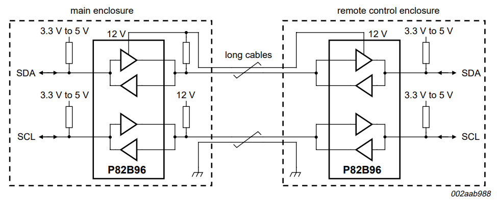
This chip uses a higher voltage level for the cable run, which increases robustness, yet still allows you to use standard digital logic voltages at either end, where your i2c devices are. That seemed a good way to go for me.
The full cable pinout I settled on:
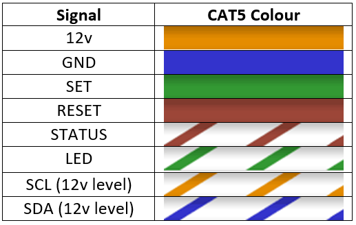
I tried to select colours that made sense by association to their function in my head. It’s important, particularly when you’re crawling around in an attic wiring something up, that you don’t have to think about which colour is for which signal. The only important requirement here was that the SCL and SDA were in a pair with the static power lines (SCL is paired with 12v, SDA is paired with GND). This pairing is to avoid switching noise creeping into the i2c signals and is alluded to in the P82B96 wiring diagram above.
With an i2c interface brought out to the remote node PCB, I figured that the most useful way to utilise this was to bring it to a connector on the remote node board (so that i2c sensor breakout boards (e.g. HDC1080 module) could easily be wired up). I also wanted to include a small port expander (PCA9536) on the remote node PCB, with its IO pins brought out to connector terminals. This port expander will make it easy to interface with simpler devices that have discrete inputs/outputs (like push buttons, PIR sensors, garage door openers etc.). To power all of the low voltage stuff on the remote node PCB, I used a linear regulator. I figured a DC-DC converter would take up too much space and was going to make the board more complicated than I wanted. Also, nothing I was planning on using was going to be overly power hungry, so efficiency wasn’t something to worry about. I selected an LDO that has both a 3v3 and a 5v version with the same footprint, so I could decide to use either voltage for any particular remote board if there was a peripheral device with a specific requirement for one of the supply voltages.
PCB Design
With all of the above decided on, I set about laying out the PCB. I typically use Eagle for my personal projects as it’s pretty simple to use and free. The place where I get my PCBs printed also accepts the eagle project file, so you don’t need to worry about generating gerbers. I just have to limit the design to two layers (a limitation of the free version of Eagle).
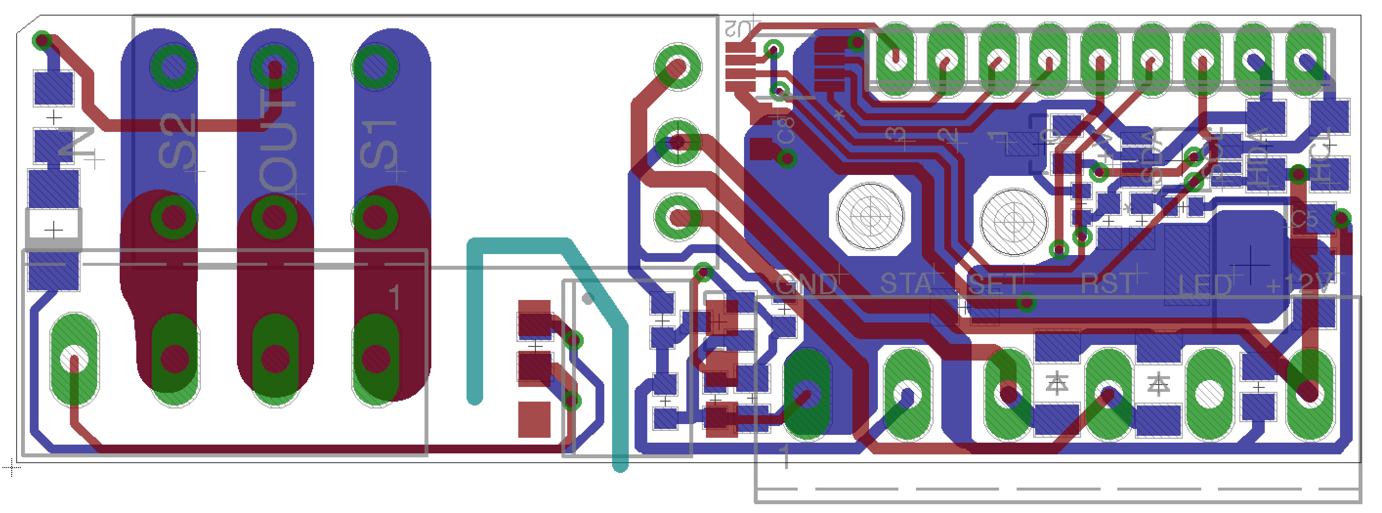
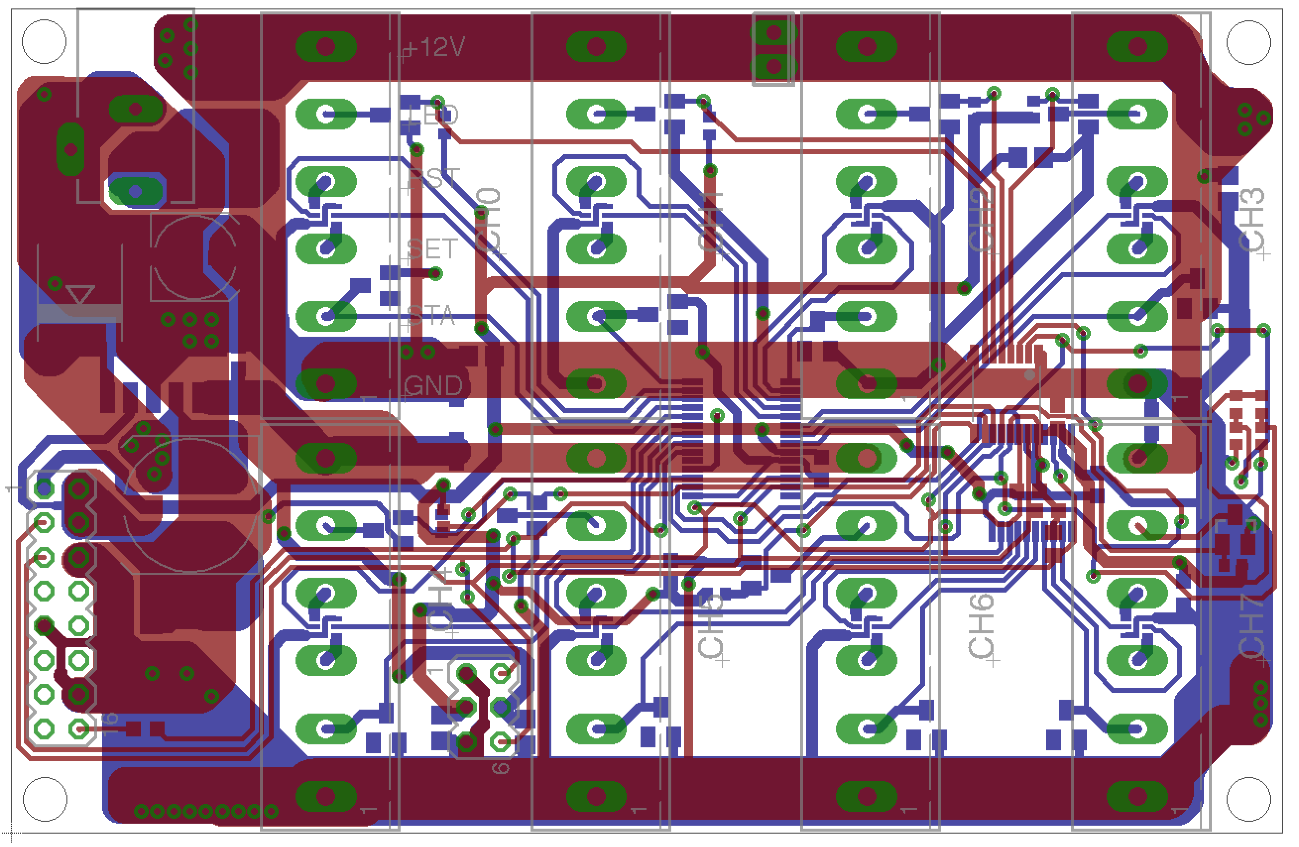
Below is an image of the layout:
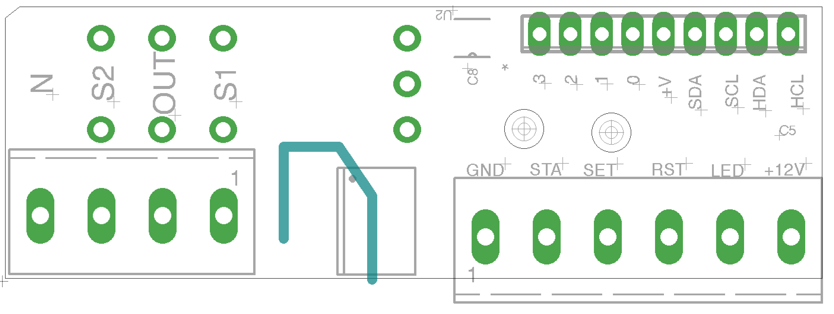
And another with the tracks hidden, so the silk screen is slightly more legible:
The main details of interest:
There are 3 connectors on this PCB: the one on the bottom left of the board is for the mains connections, the one on the bottom right has the 6 connections for the standard switch interface previously discussed and the small pitch top right connector is for i2c connections (HCL and HDA are what I called the 12v long distance i2c, SCL and SDA are the 5v/3v3 level i2c), “+V” power output (5v or 3v3 depending on which LDO is used) for external peripherals and the 4 IOs of the port expander.
All of the high voltage stuff is over to the left, with thick, high current traces between the connector and the relay pins. The opto-isolator is in the middle with an isolation cut-out underneath (the turquoise coloured line). I’d estimate the isolation between the mains domain and the controller domain is good for well over 1000V.
There are also 2 mounting holes in the centre of the low voltage side for mounting the board to stand-offs.
I got the PCBs manufactured with 2oz copper on both sides, which would further increase the current carrying capacity of the mains traces. The thick copper is completely unnecessary for all of the low voltage control signals, but you have to choose the thickness for each layer as a whole.
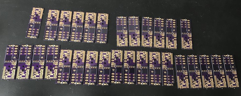
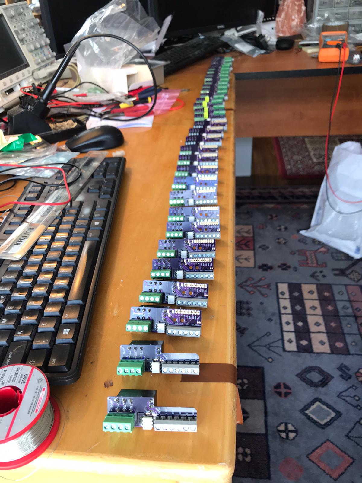
It was a serious test of both my patience and soldering skills assembling all 42 copies of this board! In the above picture of the assembled boards, there are two boards in the front that are slightly different. They were an earlier design that is just missing the i2c parts. This was a prototype stage that I only ordered 3 of to ensure the initial design was ok. They all still got used though as I didn’t need i2c at all of the remote node boards I planned to have around the house.
Controller Board Design
The controller board, while bigger and with more going on than the remote node PCB, is actually quite simple. All that is required is:
- Powering the remote nodes
- controlling of the SET/RESET lines of the relay on each channel
- monitoring of the STATUS signal
- controlling the LED indicator
- long distance i2c – but I actually dealt with that on a separate board to make the system more flexible. As I mentioned before, I didn’t need i2c brought out to every remote node.
So, taking the first 4 of the above points:
Power
The power is simple – I just made it available at the connector for each channel. I planned to use a 12v “wall wart” style PSU to power the whole control side of the system, so would have a 12v rail readily available on the PCB. I could have (maybe should have) put some current limiting protection on this, but instead, I opted for a simpler unprotected design. In the attempt of avoiding eating my own words about reliability, I’ll admit that, sure, having an unprotected power output is risky when you are installing a system or if it is a system that you regularly have to reconfigure. A short on the rail will bring the whole system down. However, once you’ve made it through the installation unscathed and the system is deployed, the risk of this happening during operation is much lower.
Switching Control
Control of the SET/RESET will be handled by an i2c port expander. The relay requires about 60mA to switch, so an output transistor is definitely required on each of these. I drove the gate of a small N-channel MOSFET directly using the IO pin of the port expander. This would be used as a low-side switch for the relay.
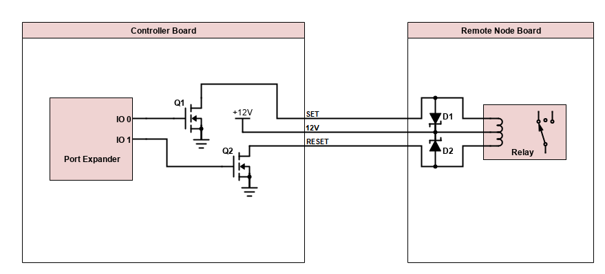
The above diagram shows how the SET and RESET signals drive the relay in the remote node. If IO 0 is set to ‘1’, the top coil of the relay will be driven. If IO 1 is set to ‘1’, the bottom coil will be driven. Needless to say, both sides of the coil should not be driven at the same time.
I should have mentioned in the last section about the remote node design, but there are two fairly beefy Zener diodes on each remote node board – D1 and D2 in the diagram. If you have worked with relays before, you may have found they can have the nasty habit of destroying their drive circuitry if you don’t take necessary precautions. The coil in the relay is essentially an inductor and inductors will try to resist changes in current. If you apply a voltage across the coil, current will start flowing in it. When you stop applying the voltage, the inductor will try to keep the current flowing and because your drive circuitry will now be seen as an open circuit (if D1 and D2 were not present), there will be a very large negative spike, possibly several hundreds of volts. This will very quickly destroy whichever transistor was driving the coil. The diodes provide a path for the inductor to dissipate its stored energy though, clamping the voltage (to about 0.7v). A standard diode will provide this “back EMF” protection, however I used Zener diodes in my design to also clamp any positive voltages that may occur. With a long cable run (and therefore other unknown inductances etc.), I felt this was an extra precaution I wanted to take. The Zeners I used had an 18v clamping voltage.
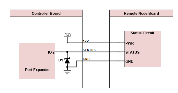
Status Monitoring
Monitoring of the Status signal couldn’t be easier – just connect it straight to one of the other IOs of the port expander. However, that is risky enough when feeding from a long cable run. I added a 3v3 Zener between the Status input and GND in order to suppress any spiking. Arguably, that is not enough protection, but I took a chance.
Indicator LED Control
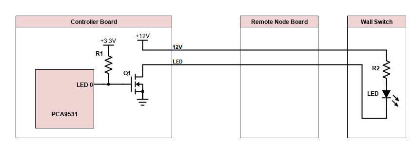
For control of the indicator LED on each wall switch, I found the following device: PCA9531. This allows the control of 8 separate LEDs, allowing the user to turn each one on/off or to set a variable brightness using PWM. There are also some other neat functions like blinking you can apply to each output. The only downside to this device is the max voltage you can supply LEDs connected to the outputs with is 5.5v. As I intended to power the indicator LEDs from 12v, I had to add an external resistor and MOSFET to each LED output. This addition will invert the operation of the PCA9531 – if you set maximum brightness, the LED will be set to minimum brightness and vice versa. This is easy to correct for in the software controlling the PCA9531.
So, the first 4 requirements of the controller board were all roughly covered. Now to make a few decisions about the PCB… Each channel requires 3 IO ports of a port expander (for SET, RESET and STATUS). If I used a 16 bit and an 8 bit port expander, that would give 24 IO ports and therefore allow for an 8 channel controller board. Also, the LED driver can drive 8 LEDs, so this matches nicely.
Component Selection and Board Addressing
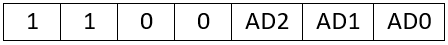
I decided to go with the MCP23016 and MCP23008. These port expanders have 3 pins (AD0, AD1 and AD2) which make it possible to set the device’s i2c address to one of 8 values (meaning up to 8 of them can be used on one bus). I won’t go into the details of how i2c works, but basically every slave device on an i2c bus has a unique 7 bit address, which the i2c master (the Raspberry Pi, in my case) uses to talk to each individually. If you look at the datasheet, you’ll see for both the MCP23016 and MCP23008, the i2c address of the device will be as follows:

I decided that the 16 bit port expander would have AD0 tied to GND (meaning AD0 = 0) and the 8 bit expander would have it tied to 3v3 (meaning AD0 = 1). The AD1 and AD2 pins from both would be connected to resistor jumpers, so that they could be tied to either 3v3 or GND on a board-by-board basis.
The PCA9531 LED driver also has 3 pins that allow you to set its address. This means the same addressing mechanism can be used for it. From the datasheet, its address is:
The best way to explain this is with a diagram. So, the first board may be set up as follows (note that R5 and R6 are populated, R3 and R4 are not):
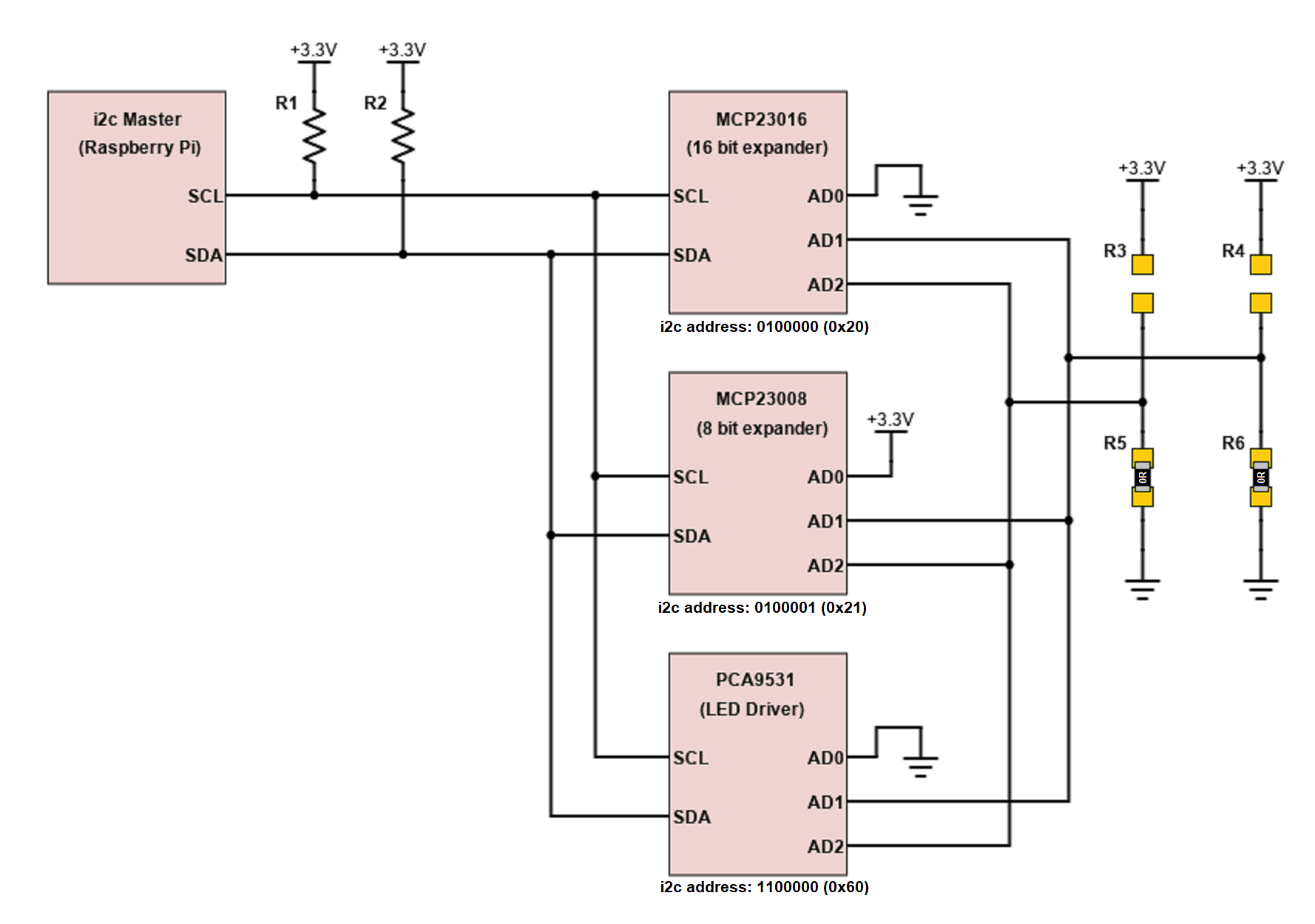
And the second board may be set up like this (R4 and R5 populated, R3 and R6 not populated):
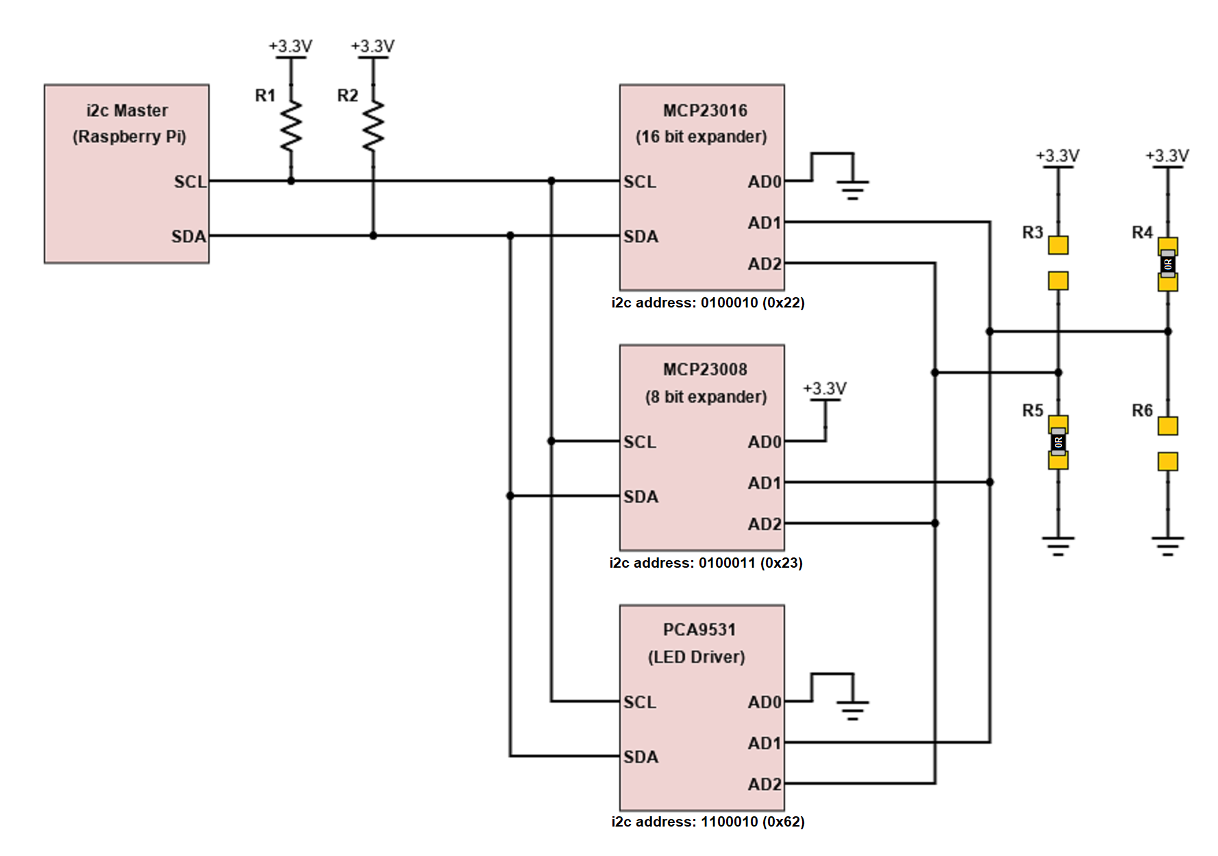
If you look at the resulting address for each slave device, you’ll see that on the second board, all 3 of them are different to all 3 of the addresses in the first, so, it would in fact be fully possible to connect both boards to one master:
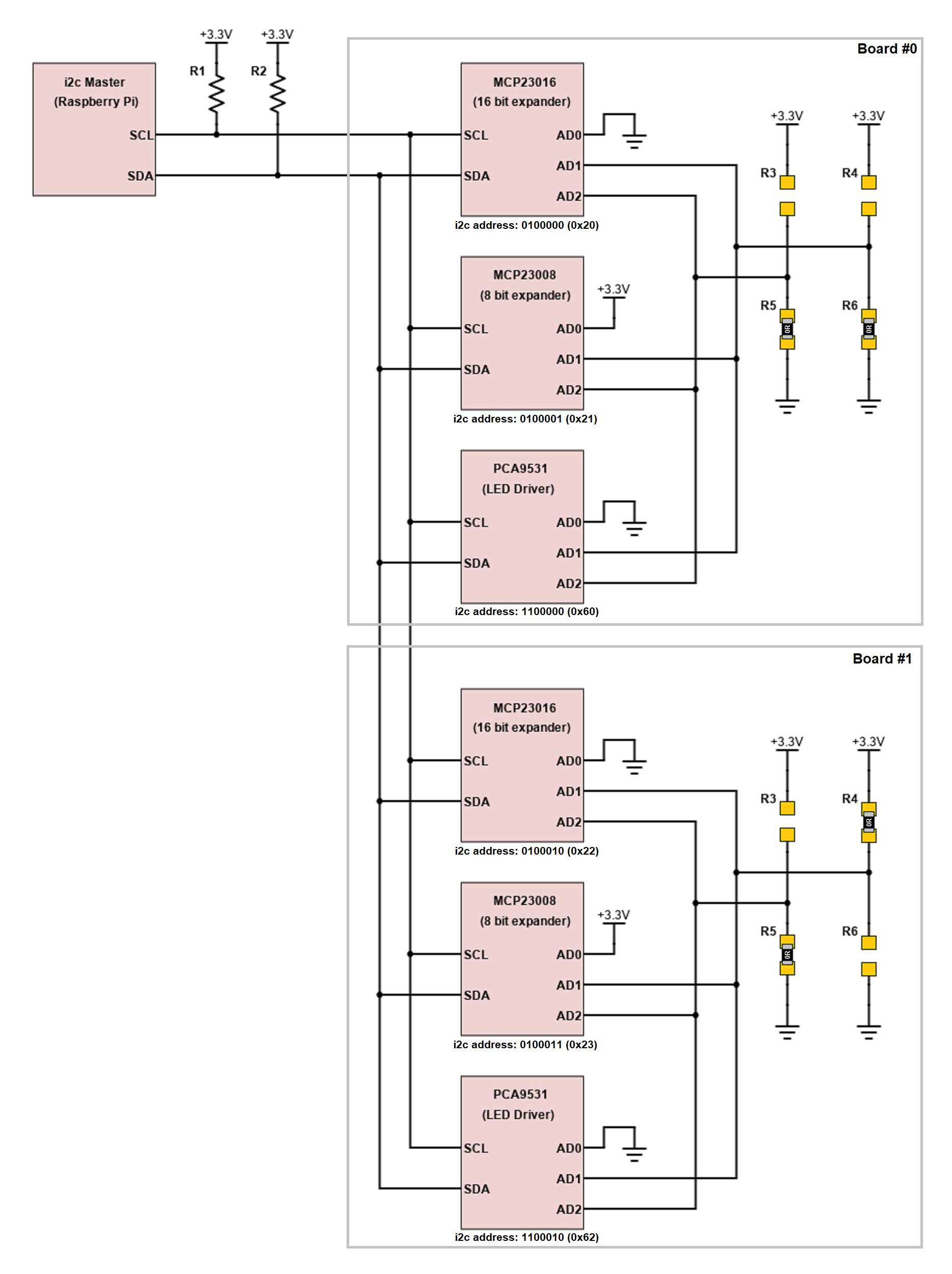
All six devices are individually addressable by the master and the only difference between the boards is the configuration of the resistor jumpers. As there are 4 possible combinations of the resistor jumpers, it’s possible to control up to 4 separate copies of the board (meaning up to 32 channels of lighting control) with one Raspberry Pi.
Interrupt from Port Expanders
The port expanders feature an interrupt output (INT). This pin can be configured so that it will be asserted if there is a change in value on any IO (or group of IOs) of the port expander. The IOs that are connected to the STATUS output from the remote nodes are the perfect use-case for this. The interrupt signal could be connected to a GPIO pin on the Raspberry Pi and the python script running on the Pi could be set to monitor the status of this pin. In the event of an interrupt being detected, the Pi can then read the input registers from the port expanders to determine which STATUS changed. The alternate to this (if there was no interrupt signal), is that the Pi has to continuously poll all of the input registers of the port expanders to check if any STATUS has changed. Using the interrupt is a lot more efficient.
The last requirement of this controller board is to provide power to the Raspberry Pi. I didn’t want to have to use the USB-C PSU in addition to the PSU for the controller board itself. That would be messy. Instead, it would be much nicer if the controller board would be able to power the Pi though the 40 pin header. All that is required is to provide 5v at Raspberry Pi pin 2 and 4 and then connect up a few GND pins also. The main supply for the controller board is from a 12v “wall wart”, so I used a DC-DC convert to generate the 5v Pi supply from this. I used a LM2576, which is able to supply about 3A and required just a few external components.
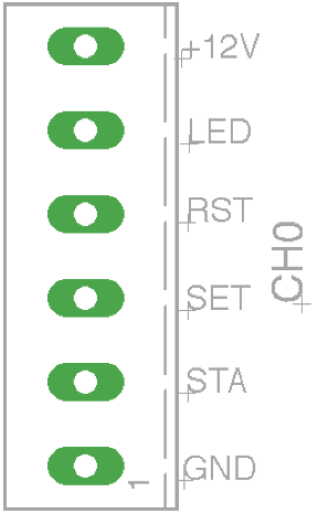
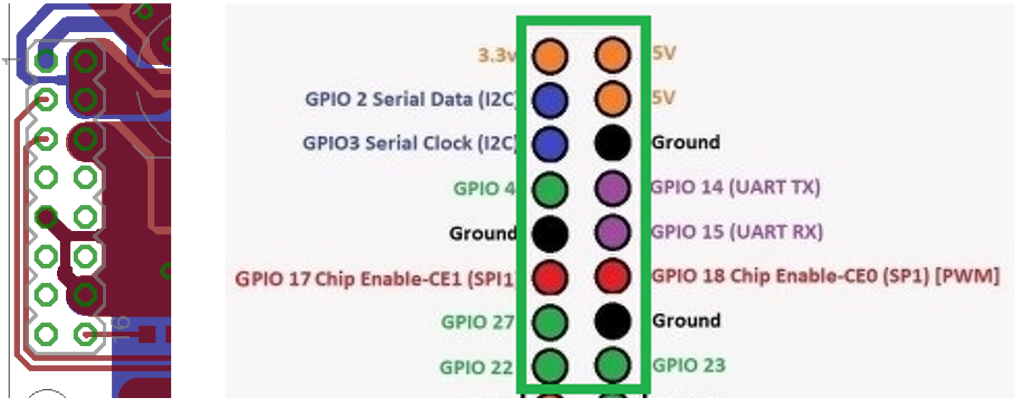
I was planning on using a 16 pin ribbon cable to connect the controller board to the Pi. This 16 pin connector would provide me access to the below pins (the first 16 at the top with the green box around them):
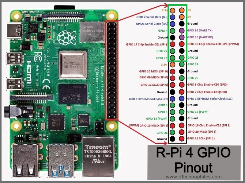
The two 5v pins, three GNDs, the 3v3 output for powering the port expanders, the two i2c pins for controlling everything and a few GPIO pins also are all accessible, so that’s everything I needed.
PCB Design
The PCB design came together ok. It was a bit challenging to get everything connected up on only 2 layers, but I managed it by remapping the IO pins of the port expanders in an order that prioritised clean layout. What I mean by this is instead of a nice order that you might initially choose:
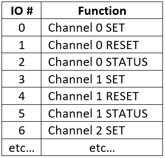
The order is actually all over the place when you look at it on paper:
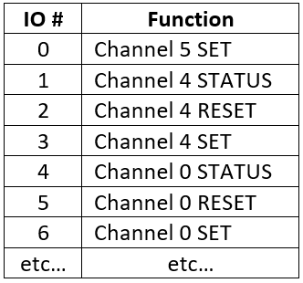
But this order minimises the amount of tracks that would have to cross over each other on the PCB. It is easy to apply the inverse of this remapping in the software. Complete layout shown below:
There are 8 connectors on this board for connecting to the 8 remote nodes. They have the same pinout as the connector on the remote node board:
On the right side of the PCB, you’ll see the resistor jumper options for assigning the “address” of the board

On the left side is the connector for the Raspberry Pi
All 5v, 3v3, GND connections can clearly be seen, along with the i2c bus and GPIO 23, which will be used as the interrupt from the port expanders.
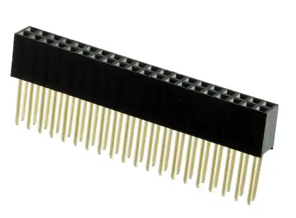
This connector can be stacked using the below style of connector (the same way you can stack Raspberry Pi hats), which is how multiple copies of this board can be connected up.
Only one of the boards would be required to have the 5v DC-DC converter components fitted, but the rest of the components could all be fully populated. In the end, I actually designed another, slightly different controller PCB to be used as boards for the extra channels (i.e. channels 8+). The main reason for this respin was that I wanted to use a relay drive transistor that was easier to solder (the original design used a dual transistor in a SOT-363 package, which is a nightmare to solder by hand if you’re not particularly skilled).
I took the opportunity to add some extra options for connecting the interrupt outputs from these boards to different GPIO pins (see bottom left) and also added another connector in place of the 5v DC-DC circuitry (which would have been unpopulated on this board anyway). This connector would be used for connecting up some indicator LEDS and maybe a button or two on the front panel of the cabinet I was going to house the controller in. It connects these to other unused Raspberry Pi GPIO pins.

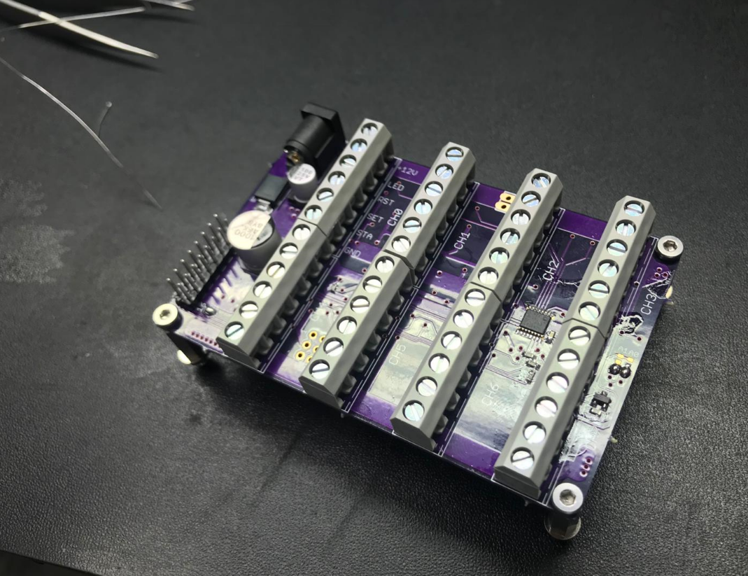
Some photos of the assembly:

Long Range i2c Mux Board
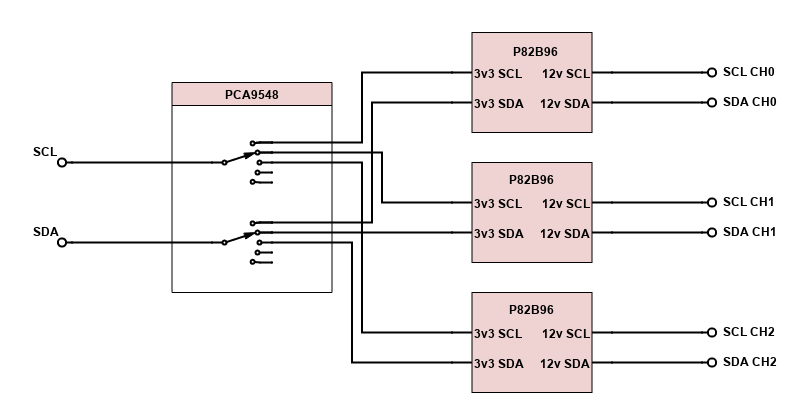
The previous PCB handles the control of all of the basic switching on the remote nodes. The long range i2c has still not been addressed, though. The fact that there will be multiple remote node boards of the same design means that there will be multiple i2c devices at the same address. Even if it were possible to individually set the address of these devices by bootstrapping (like I did with the port expanders), this would be a very difficult system to deploy and keep track of. Instead, I decided to go the route of multiplexing the i2c bus using a PCA9548. This handy device allows you to split an i2c bus up into 8 separate “channels” and talk to devices on each channel separately.
I planned to use this i2c mux followed by 8 of the P82B96 (long range i2c) devices used on the remote node board. The basic block diagram concept of this PCB is as follows (just the first 3 channels of 8 shown):
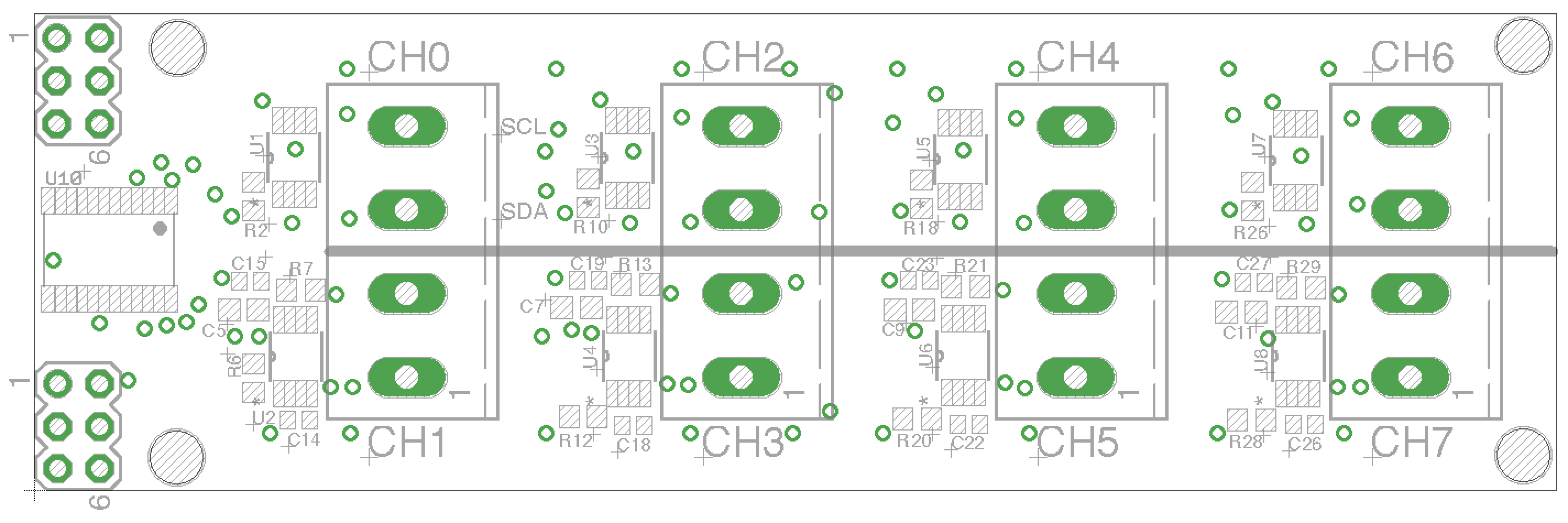
PCB Design
I was able to fit this on a smaller PCB than the main controller board. The PCA9548 mux chip is over on the left and each P82B96 is beside its channel’s connector.
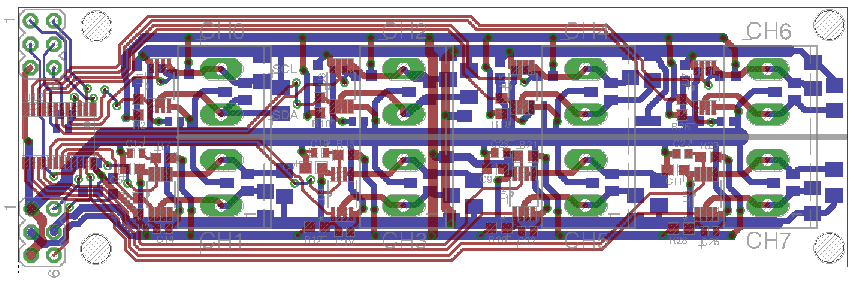
And with the tracks hidden for clarity:

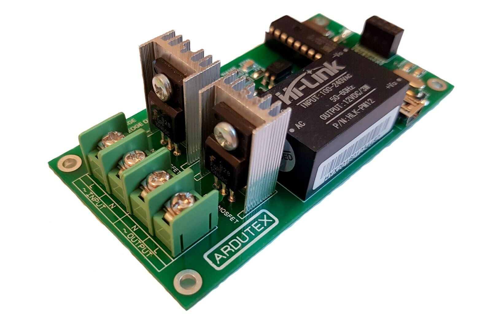
Dimmers
I didn’t fancy my chances at designing my own mains dimmer, so I searched around a bit and found this excellent product from Krida Electronics. It fit my needs exactly, being controllable by i2c and is extremely good value at only €30 per unit. It’s also a trailing edge dimmer, which means that it works well with dimmable LEDs. A trailing edge dimmer’s pass devices turn on at the zero crossing of the mains waveform as opposed to a leading edge dimmer’s, which turn on at some point during the non-zero portion. It doesn’t make any difference which dimmer type you use if you are dimming incandescent bulbs, however LED light fixtures have decoupling capacitors in their PSUs and the abrupt rise in voltage on a leading edge dimmer’s output will lead to large inrush currents flowing at every cycle. This can lead to component fatigue and flickering of the light fixture. Anyway, I have 10 of these around the house. They integrate well with the remote node boards. They sit after the switch of the remote node board in terms of the mains wiring and are controlled by the i2c interface and powered by the 5v output that are both available at the remote node’s connector.
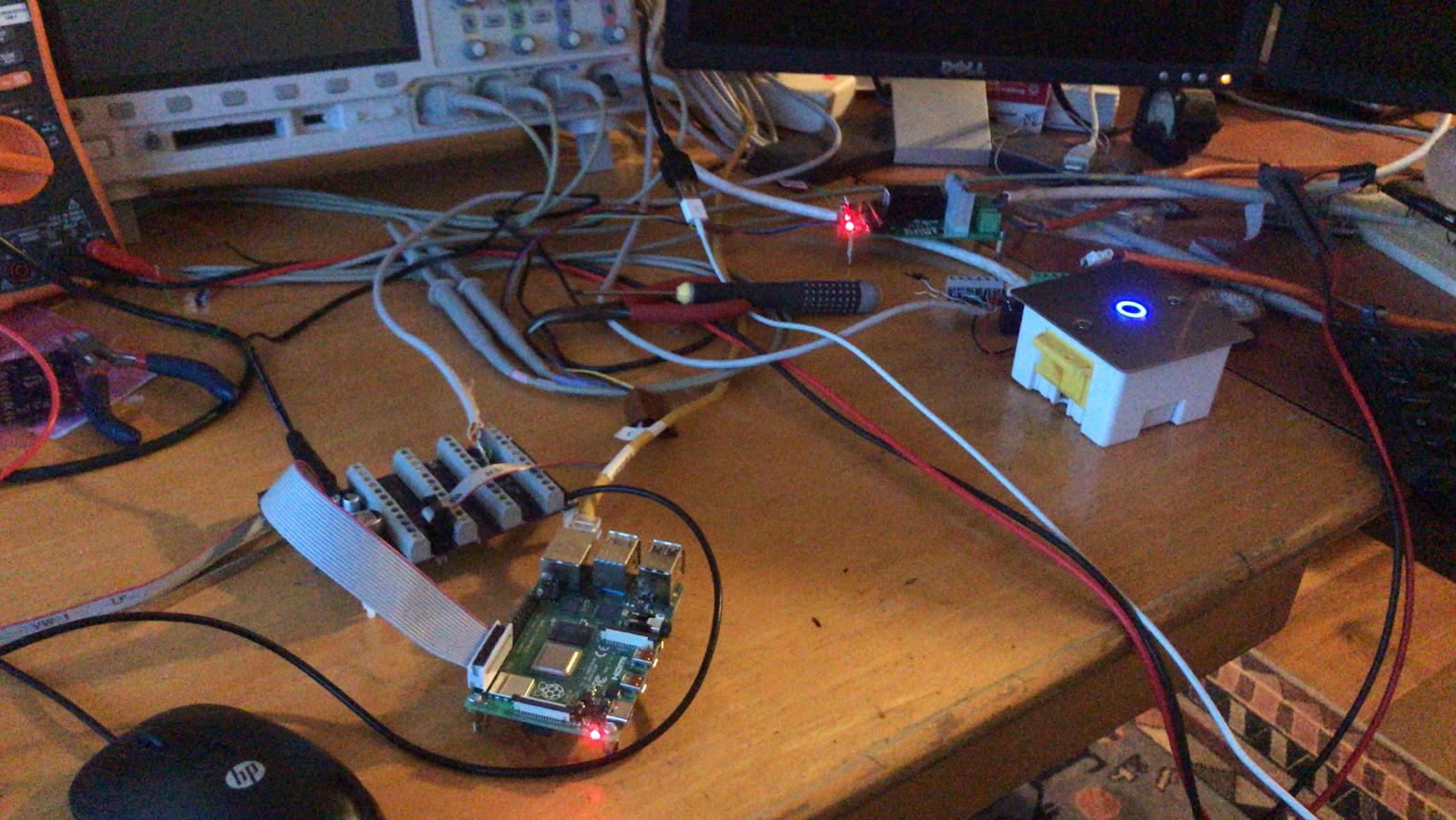
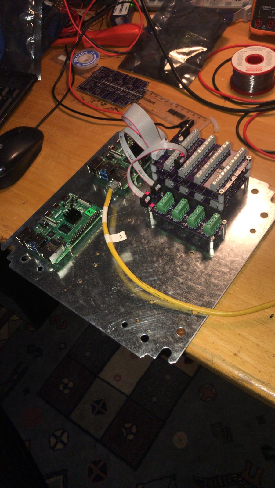
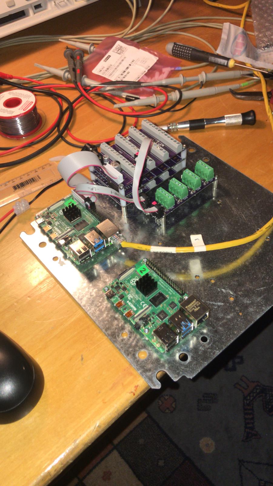
Board Bring-up and Testing Photos
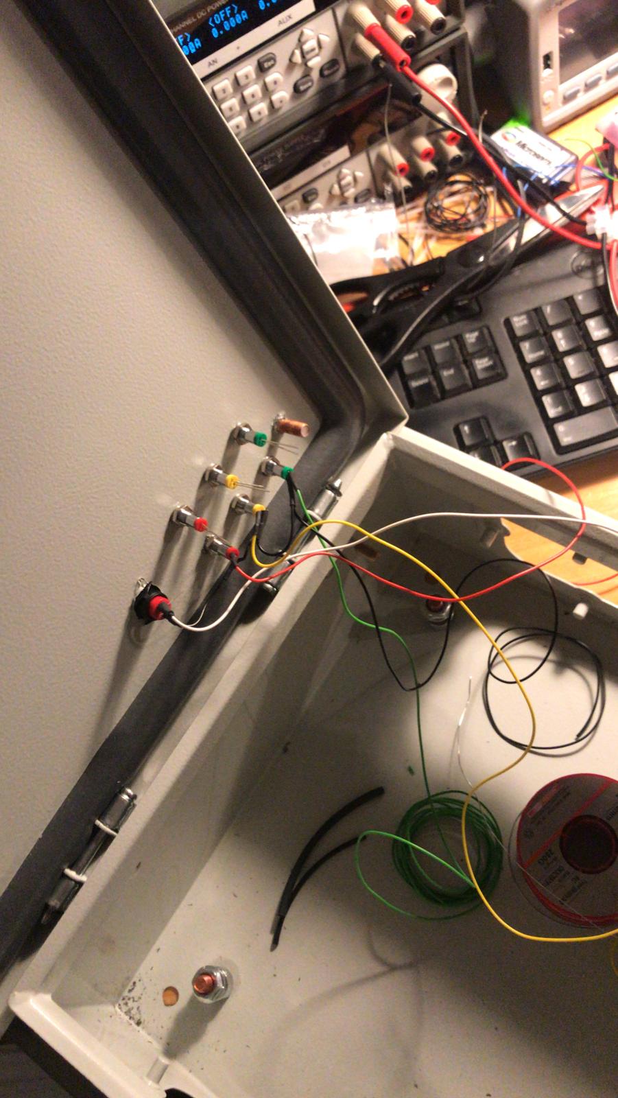
Installation Photos
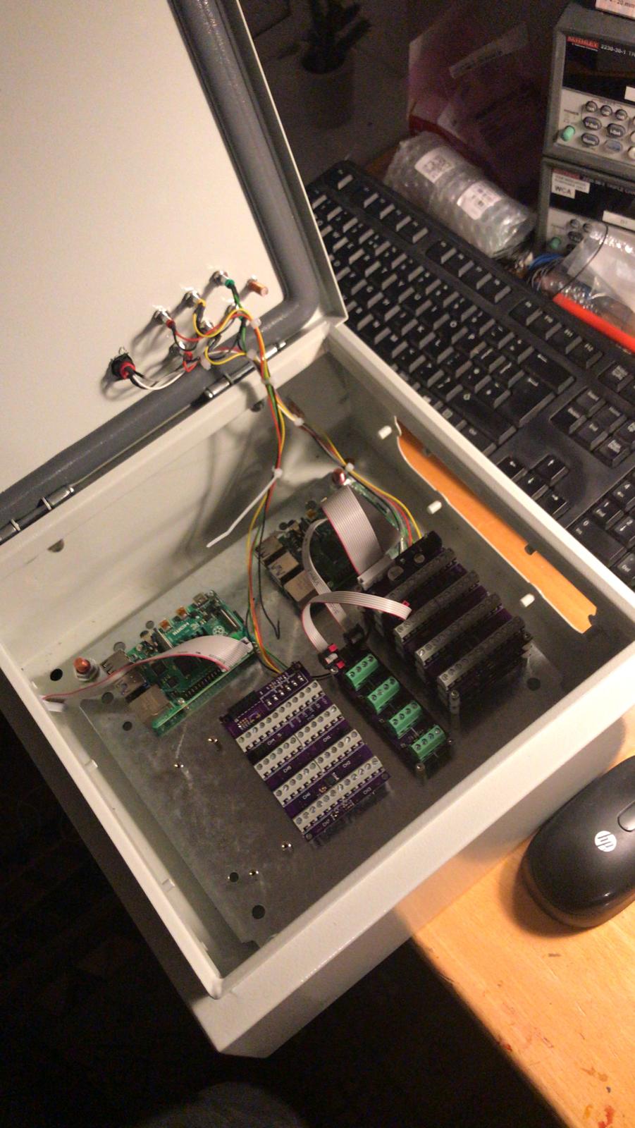
The cabinet where the controller is housed is mounted under my networking rack in my office. In the end I opted to use 2 separate Raspberry Pis: one for everything downstairs (with 3 controller boards and 2 i2c mux boards, for a total of 24 controllable channels and 16 long range i2c channels) and the second one for everything upstairs (with 2 controller boards and 1 i2c mux board, for a total of 16 controllable channels and 8 long range i2c channels).

A bit of a rats nest inside, but it thankfully all fit and is hidden from view once the door is closed!
There are some small “afterthought” prototype boards hanging in front of the controller boards. They are to enable a remote power-cycle of each Raspberry Pi, as a last resort if either becomes non-responsive.
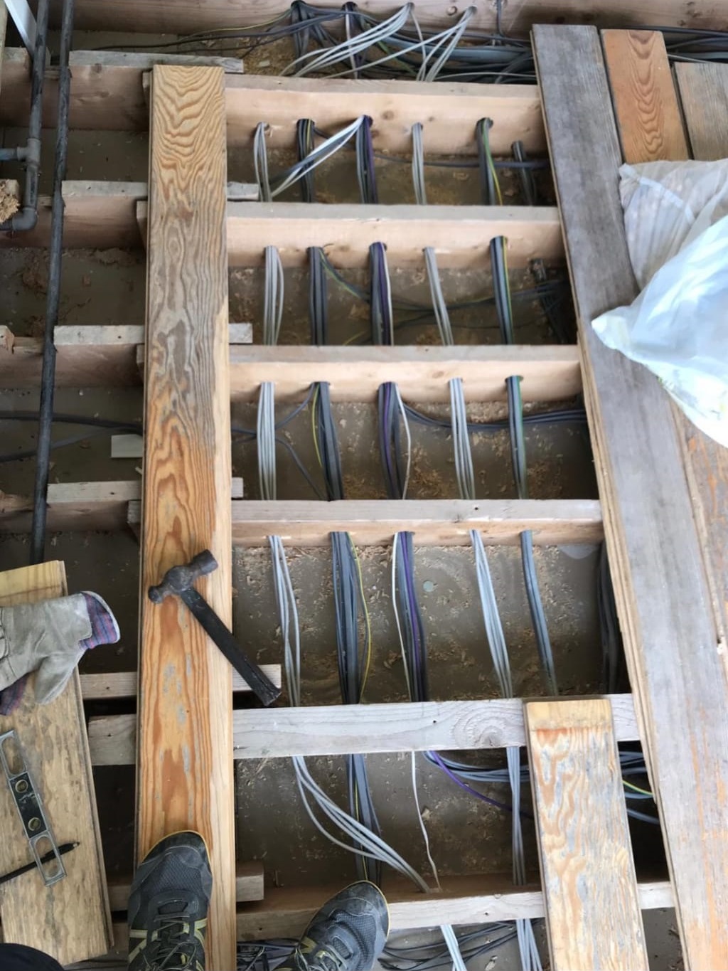
The hidden wiring under the floor ended up a lot neater as luck would have it… This is under the landing which is the main route most of the cabling took out to the rest of the house. All in all, I think I added about 1.5km of cabling!
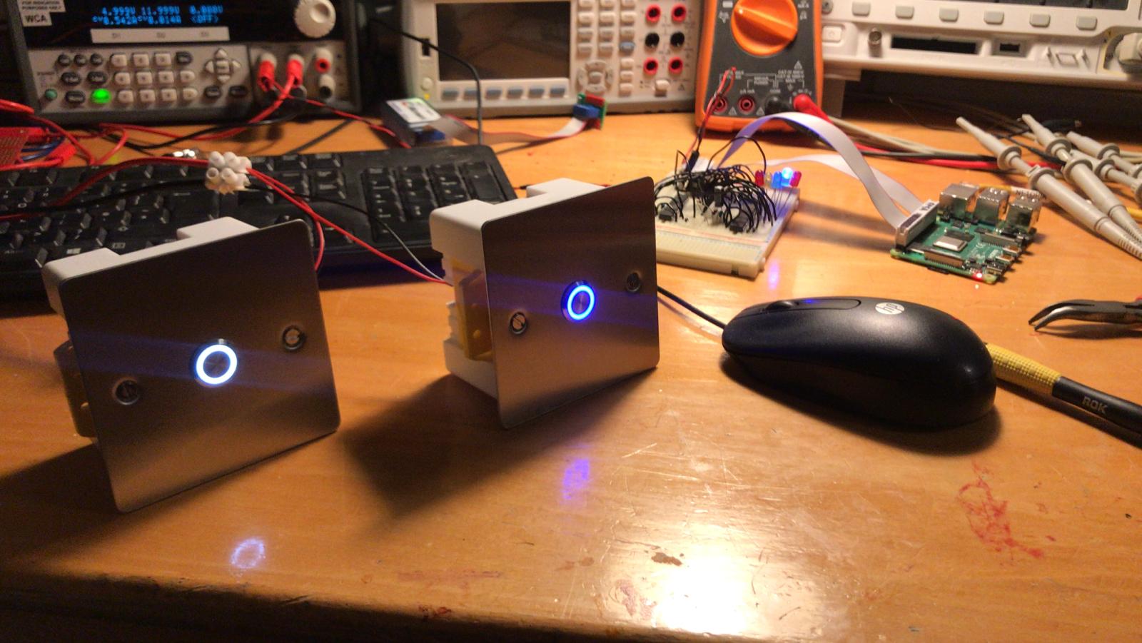
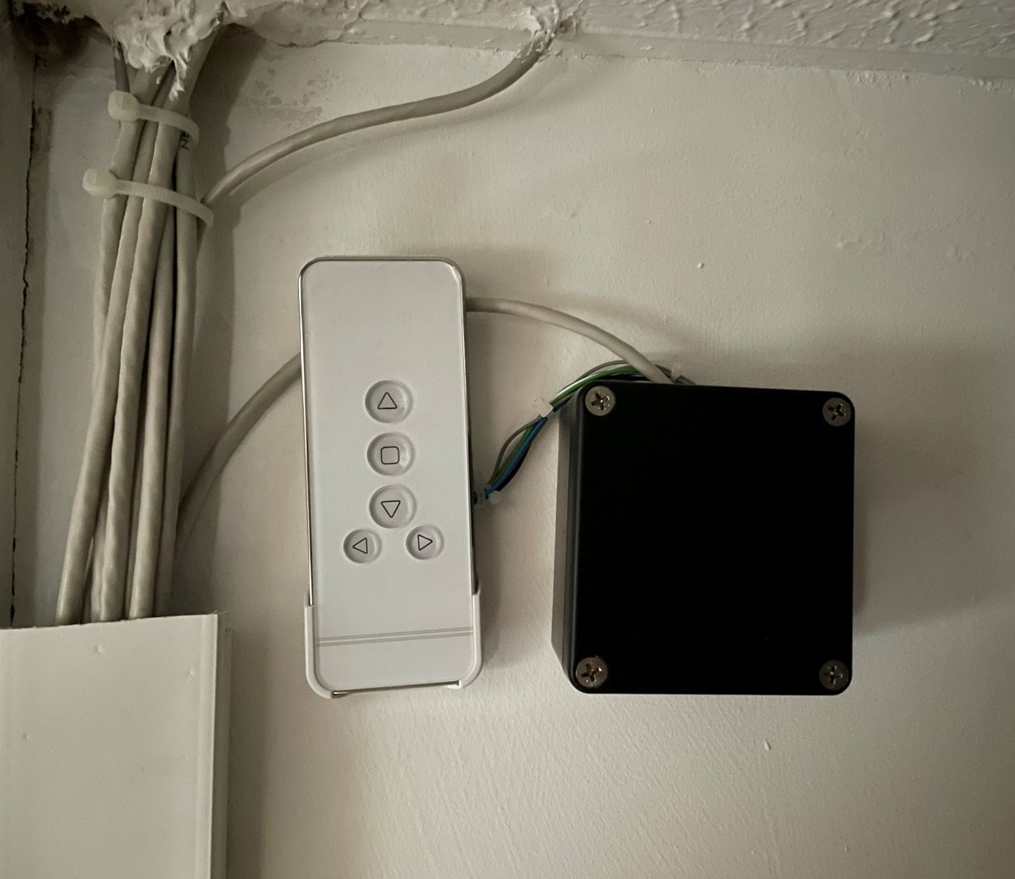
I hand-made the wall switches for use in each room (with great difficulty… I hadn’t realised how hard stainless steel would be to drill!). The convention I went with was white is an actual switch that switches the main light in the room, blue is a button that is connected to one of the I/Os on the remote 4 bit port expander and so can be programmed to do something a bit smarter (e.g. recall a scene)
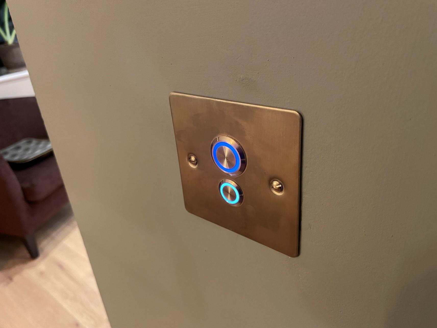
I used switches/buttons from the manufacturer EAO: Blue button, white switch. They were expensive, but have a very premium feel. The backplate is just a blanking plate from screwfix.
A smart plug in the kitchen so the kettle can be boiled remotely:
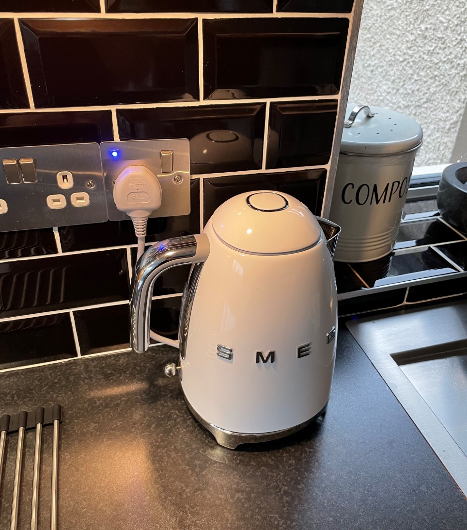
I used the standard remote node board for this, however, soldered extra wire between the connector and the relay pins as, even though the PCB traces I used were thick, I didn’t quite trust them to carry the 10-12 Amps the kettle would draw.
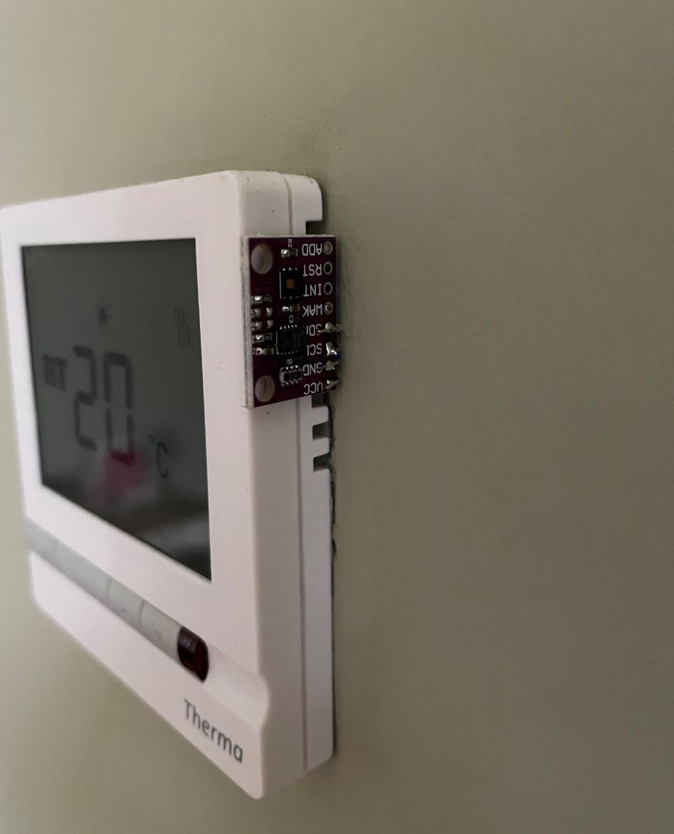
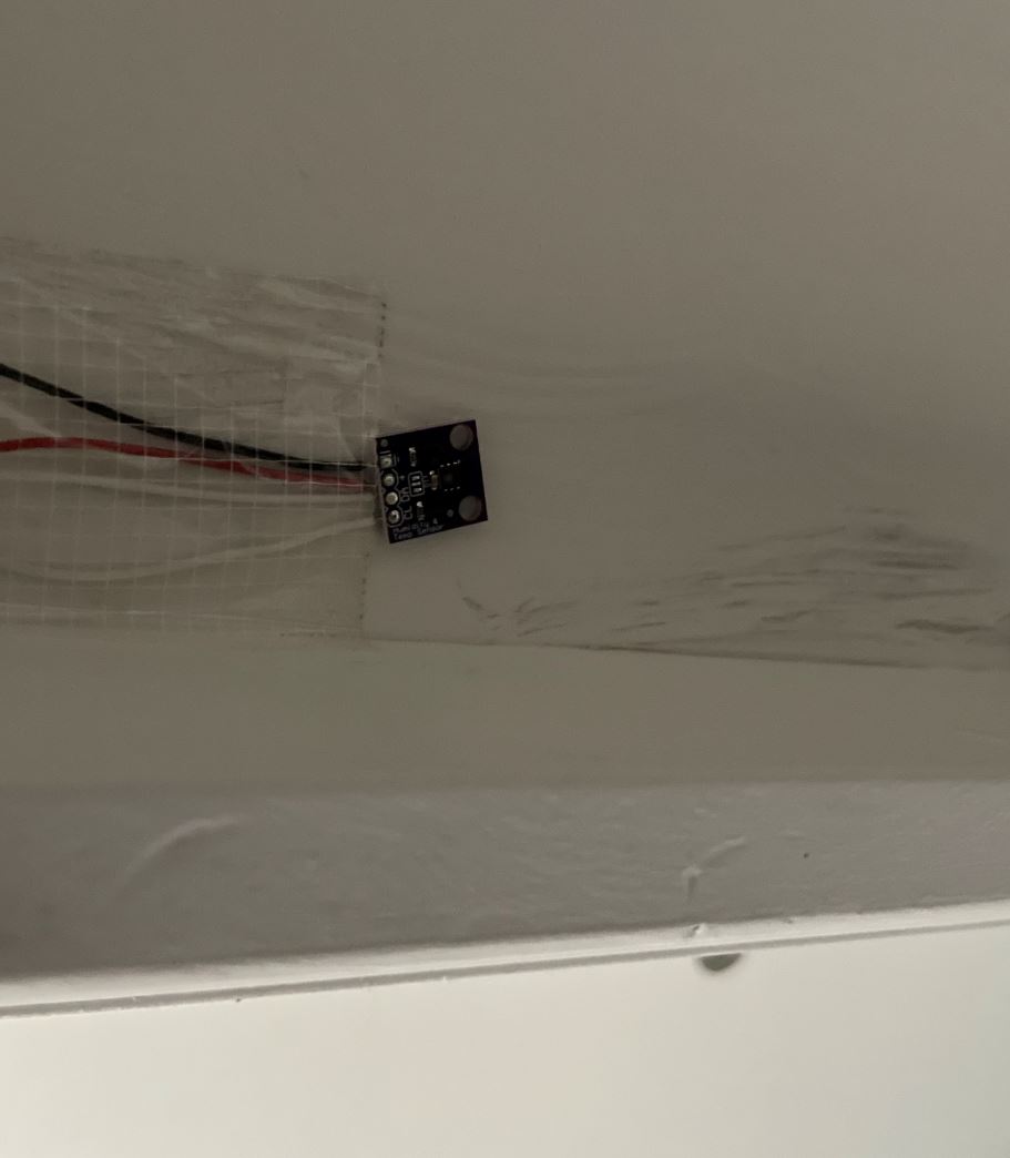
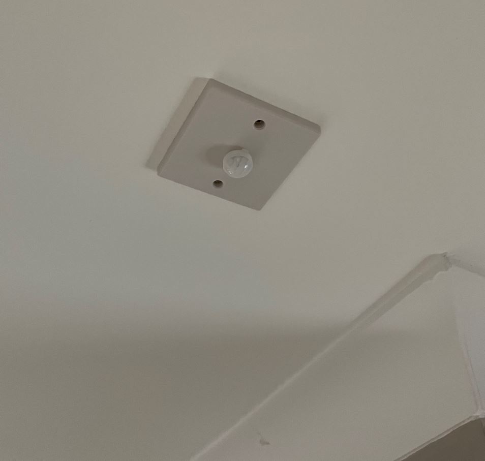
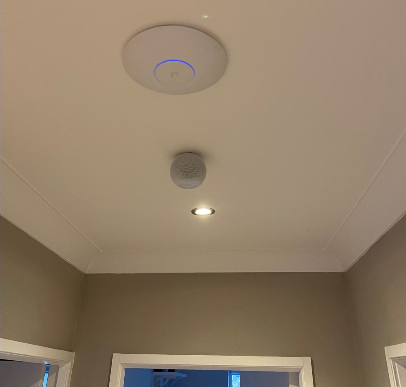
There’s a whole host of i2c sensor boards that connect to the closest remote node board:
Software
As I mentioned previously, I was planning on using Homebridge as the interface between Apple Home and my custom design. This is a fantastic development which is extremely useful if you want to control devices that do not have native HomeKit support.
I installed Homebridge on my Raspberry Pi by following these instructions on their github page. I skipped on the install of the GUI (by removing “homebridge-config-ui-x” from the npm command) as I planned to configure it manually using the config.json file and I didn’t want the GUI to be running in the background when I didn’t need it. I also set up Homebridge as a service so it would start automatically on boot.
Script2 Plugin
The first plugin of interest to me was Script2. This is an extremely simple and efficient plugin that allows you to add switches to Homebridge. You need to generate your own scripts that will be executed when the switch is turned on and off (I just created simple one-liner .sh files, one that creates a file called input_on.sh and one that removes it called input_off.sh). An example of the way that you add a switch to your config.json file is shown below:
{
    "accessory": "Script2",
    "name": "Kitchen Centre",
    "on": "/var/lib/homebridge/input_on.sh 2 0",
    "off": "/var/lib/homebridge/input_off.sh 2 0",
    "fileState": "/var/lib/homebridge/state_2/0",
    "on_value" : "true"
},
You give the switch a name, an on command, an off command and a path to a file whose presence indicates the current state of the switch. The arguments that my input_on.sh and input_off.sh scripts take in dictate the folder name and the filename that will be created or removed. In the case of the above example a file called “0” (from the second argument, “0” in this case) will either be created or removed from a folder called “input_2” (from the first argument, “2” in this case).
An example of this working is shown below. So, with the centre light in the kitchen turned off, if I look in the “input_2” folder on the Raspberry Pi, the folder is empty:
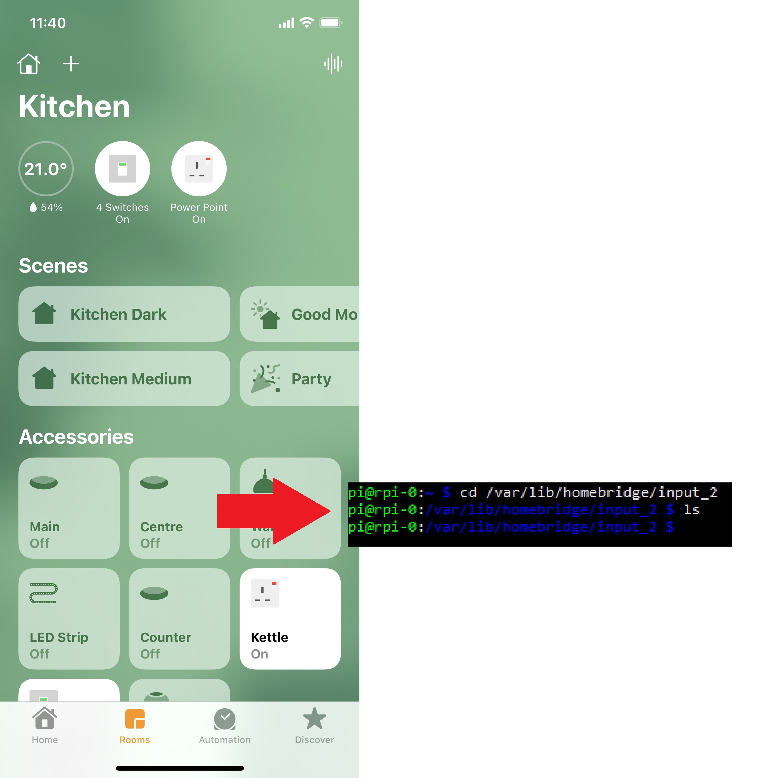
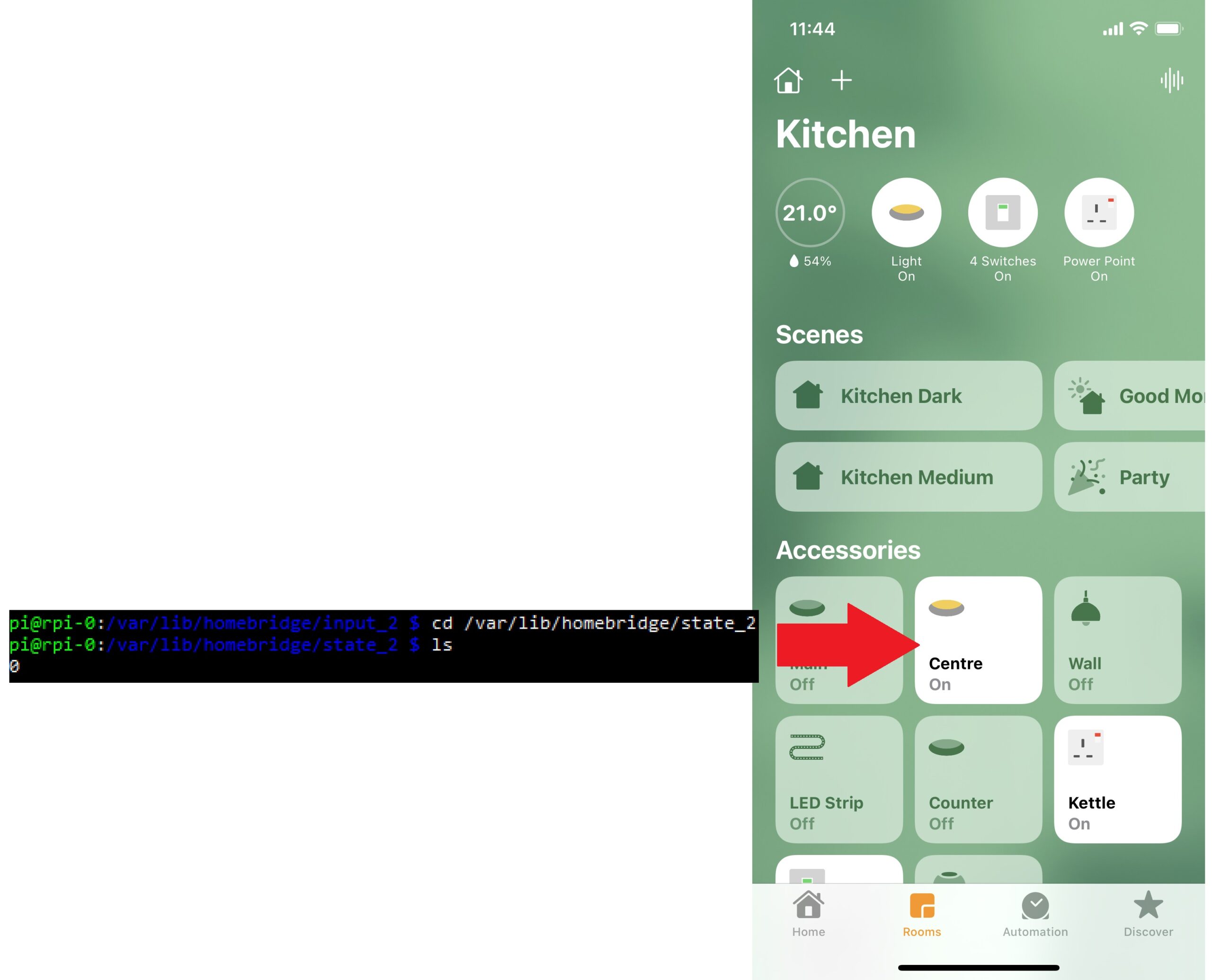
However, if I turn on the centre light, and look in the folder again, a file called “0” has been created:

In order for the smart controller to take action on that, all it has to do is monitor the timestamp of this folder and then control the hardware appropriately (i.e. turn on/off the correct relay) when the corresponding file is created or removed.
I wrote a python script to handle all control of the hardware. It checks the timestamp of the input folders regularly using:
for i in range(num_boards):
    last_ts_switch[i] = new_ts_switch[i]
    new_ts_switch[i] = stat(r'/var/lib/homebridge/input_'+str(i)).st_mtime
    if (last_ts_switch[i] != new_ts_switch[i]):
        # check which files are present and take action
I have a separate “input_” folder for each board, so, as you can see from above, the centre light in the kitchen is channel 0 on board 2, which is why the filename is “0” and the folder is “input_2”.
The hardware is also able to measure the current status of the light as I mentioned in a previous section. The controller script updates files in another set of folders based on the current status of the light. These folder names begin with “state_”. When the centre light in the kitchen is turned on, the STATUS circuitry on the remote node for this channel detects this and sets the STATUS signal to ‘1’. The port expander that is connected to this channel back in the controller detects this change and asserts an interrupt, which triggers the python script to poll the port expander and determine the status of the channel. The file in the “state_” folder is then created or removed as appropriate, which is picked up by Homebridge. As you’ll see from the excerpt from the config.json file above, the “filestate” setting points to this file:
"fileState": "/var/lib/homebridge/state_2/0",The icon in Apple Home then lights up to show the user that the light is currently on:
As I mentioned, this Script2 plugin is extremely light-weight and efficient. I have about 50 instances of it running on a single Raspberry Pi and there is no observable decline in performance. Operating any of the Script2 controlled accessories is extremely responsive.
Cmd4 Plugin
Knowing that I wanted to be able to control more than just on/off light switches in the house, I went in search of something more sophisticated. Cmd4 allows you to create pretty much any type of virtual accessory and is in the same vein as Script2 in that, the statuses of these accessories are reflected in files on the Raspberry Pi. This plugin is significantly more difficult to set up, however that goes hand-in-hand with a plugin that has many more features. Presumably also because of the increased complexity, it’s nowhere near as responsive as Script2 and also seems to be quite resource intensive. I tried adding all accessories that I wanted to have in the house onto one Raspberry Pi and I noticed the core temperature had sky rocketed over 70°C and the response time of all the accessories had reduced to a crawl. This may well be down to a fault on my part in the configuration of the plugin, but I haven’t been able to find a way around it unfortunately. For this reason, I’ve had to limit the amount I use this plugin, however its flexibility is extremely handy. At present, I’m using it for control of my blinds, garage door, security system and smart sockets. I also use it for monitoring temperatures, humidity, air quality and also motion sensors. In order to add accessories, you have to add Cmd4 as a platform to the config.json and from there, you can define accessories within. Taking an example of a Temperature Sensor, this is how I have it configured in my config.json:
{
    "type": "TemperatureSensor",
    "displayName": "Temperature_0",
    "currentTemperature":        50.0,
    "name":                     "Temperature 0",
    "stateChangeResponseTime":   3,
    "state_cmd": "node /var/lib/homebridge/Cmd4Scripts/State.js"
},
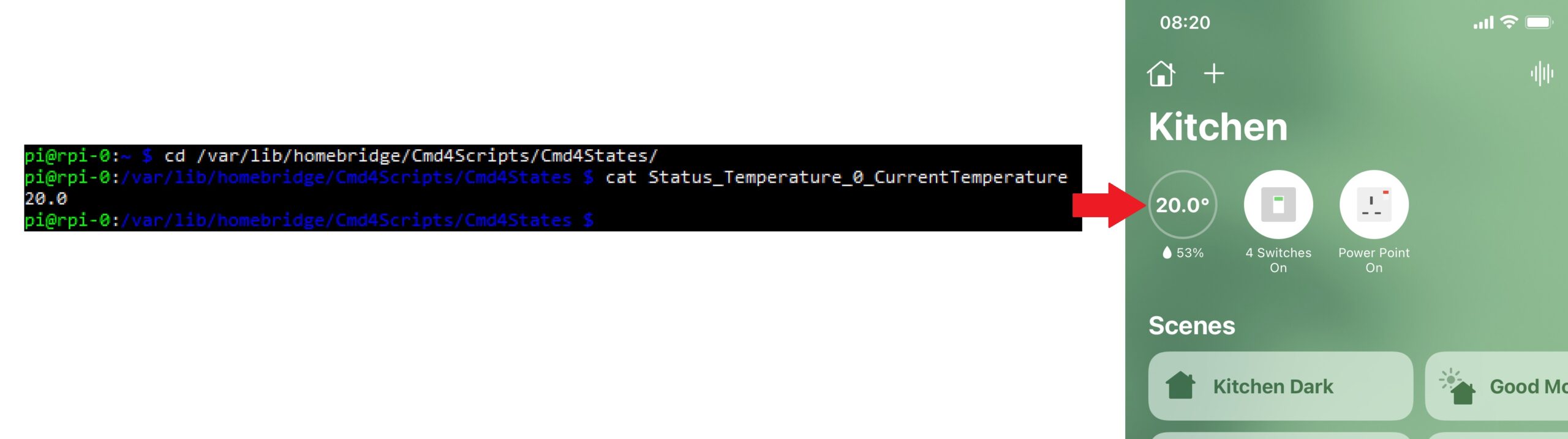
You need to give the accessory a display name, which will be used in the status file. The current temperature parameter has to be given a default value, which is why “50.0” is shown above.
In order to update the displayed temperature, I need to write into a file called “Status_Temperature_0_CurrentTemperature”. Once my python script reads a new value from the temperature sensor, it writes it into this file. As can be seen below, this value is then displayed by the accessory in Apple Home.
Taking a more complicated example, like the garage door:
{
    "type": "GarageDoorOpener",
    "displayName": "GarageDoorOpener",
    "currentDoorState":         "OPEN",
    "targetDoorState":          "OPEN",
    "obstructionDetected":      "FALSE",
    "name":                     "GarageDoorOpener",
    "polling": [
        {"currentDoorState":     "OPEN",      "interval": 540, "timeout": 8000}
    ],
    "stateChangeResponseTime":   3,
    "state_cmd": "node /var/lib/homebridge/Cmd4Scripts/State.js"
},
This requires 3 files: target door state, current door state and obstruction detected.
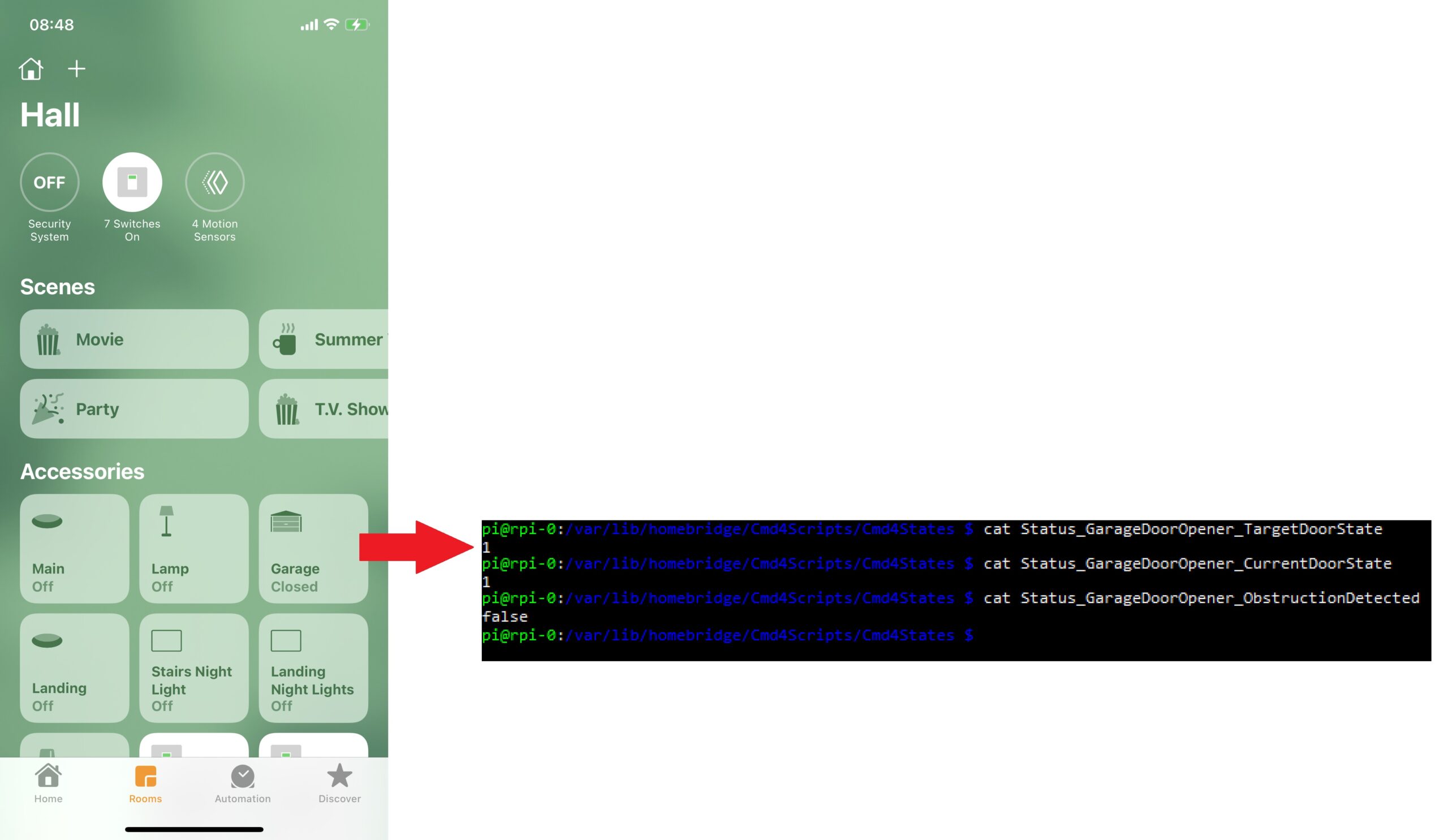
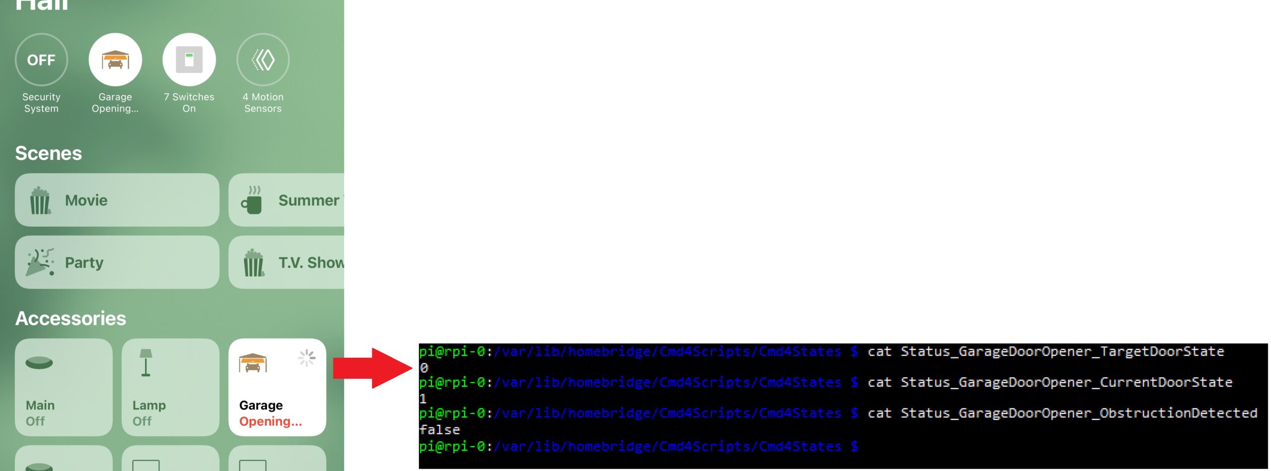
The target door state file is the file that will actually control the door. This gets modified when you press on the button to open the garage.
The other two files are status files for feedback to the user. I have magnetic switches mounted on the track of the garage door opener (open and closed sensors shown below)
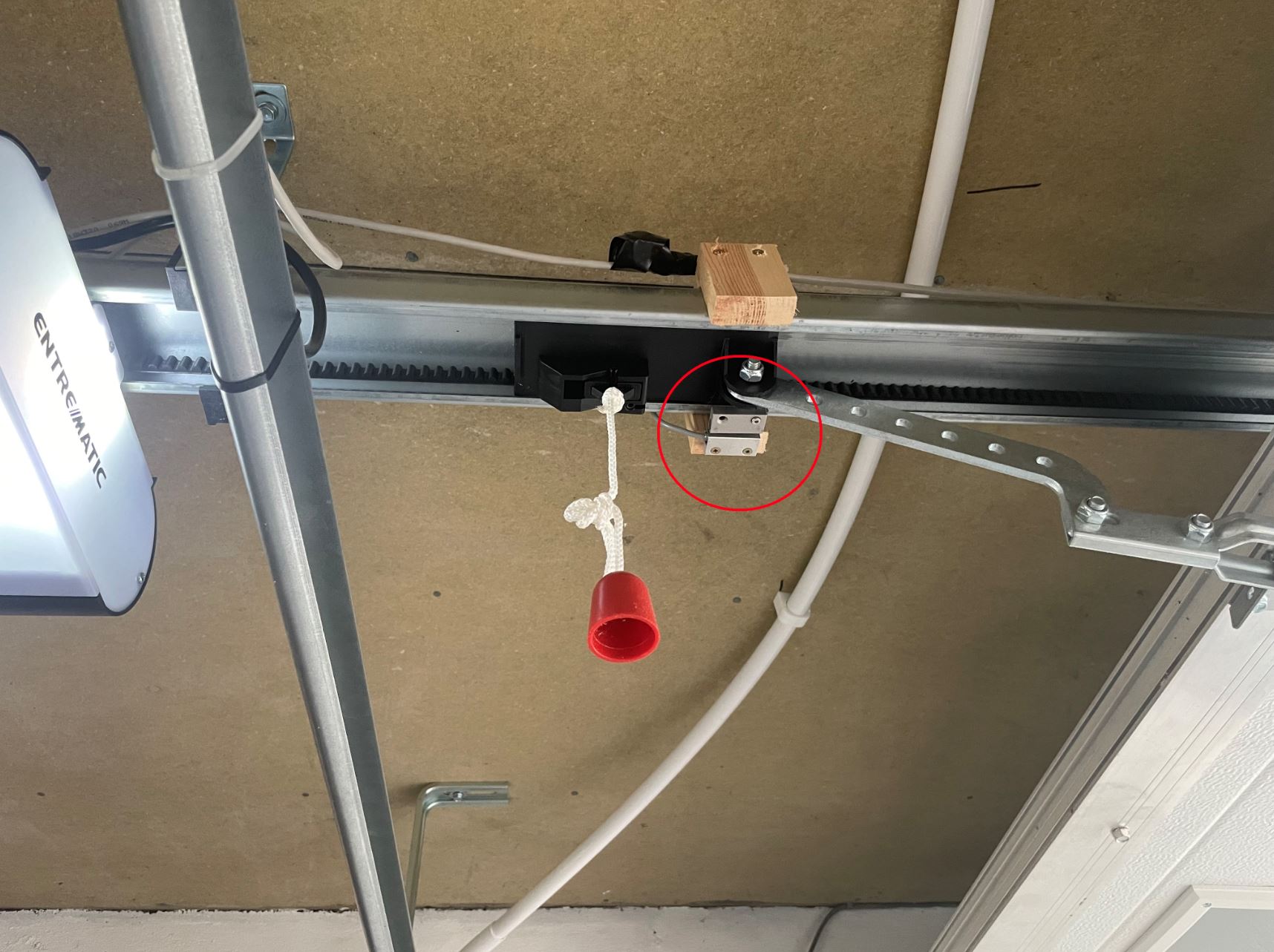
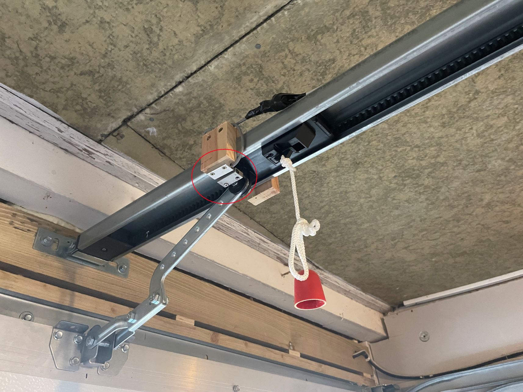
Once the open/close action is detected as being successfully complete, the current door state file is updated by the python script.
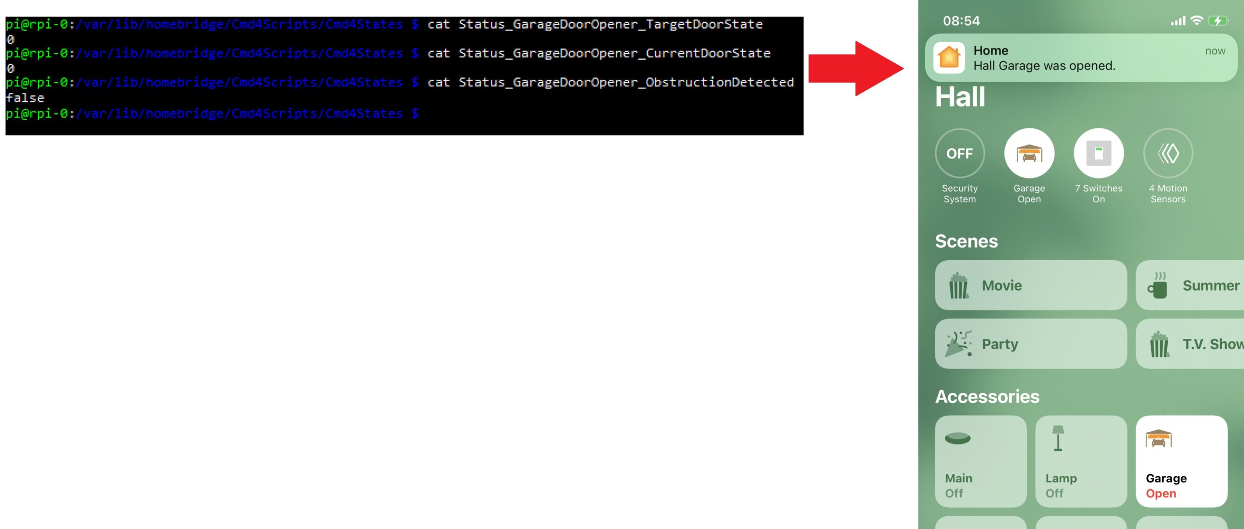
I don’t currently write into the obstruction detected file (just leave it permanently set to false), however it would be possible to utilise this if the garage door was detected as being neither closed nor open for an extended period.
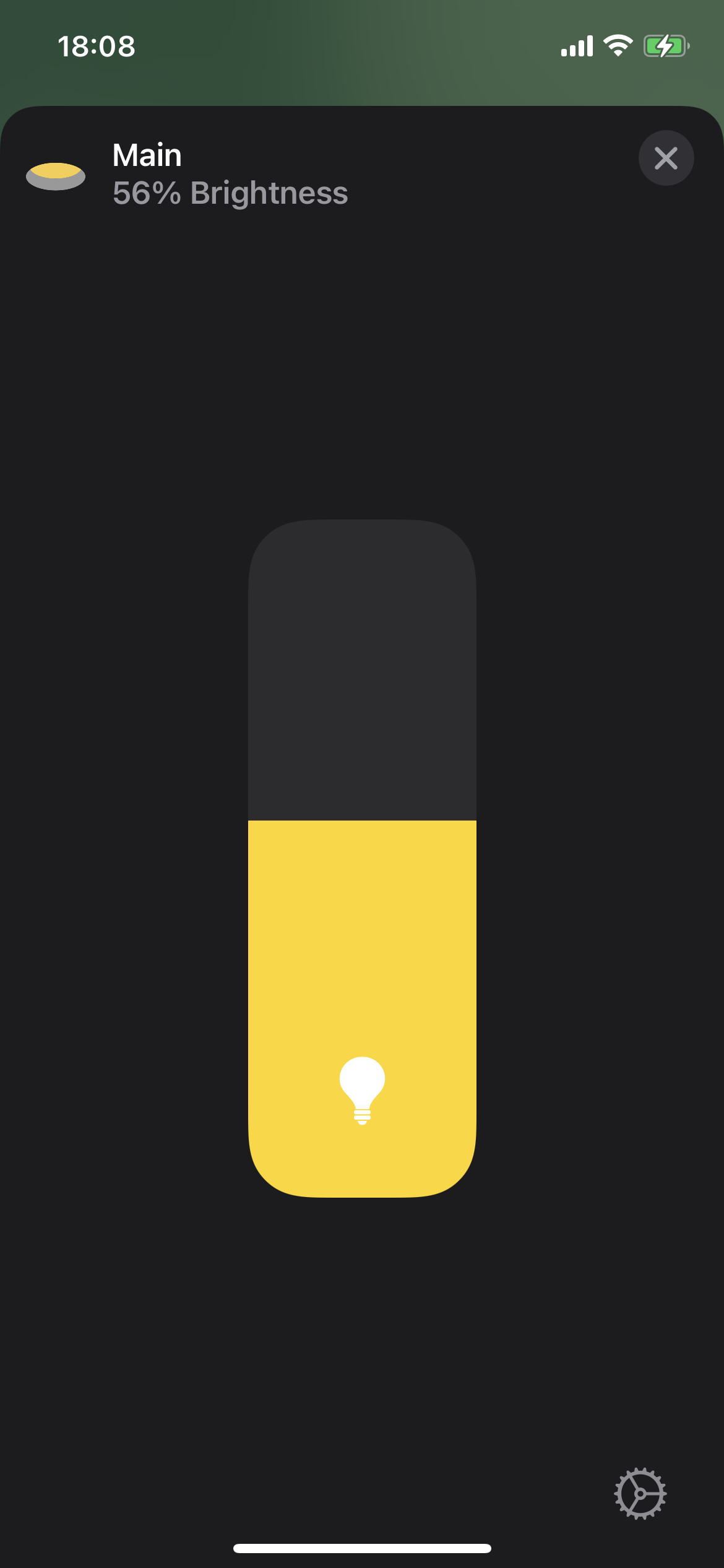
HTTP-Lightbulb Plugin
I had initially been using the Cmd4 Plugin for my dimmable lighting control. As I already mentioned, I’ve found this plugin to be a little sluggish and lighting control is something where you do notice this quite a lot, particularly if you’re using the slider in the app for setting a particular brightness.
I found the HTTP-Lightbulb plugin and started researching it. On investigating what would be required to get it up and running with my setup, I wasn’t overly optimistic that it would improve the responsiveness, but I proceeded nonetheless.
I wrote a python script that was going to act as a http server – a pretty simple script based on the BaseHTTPServer library. This supports the http PUT and GET requests from the plugin.
The way I set up the plugin up for a simple dimmer in the homebridge config.json file is as follows:
{
    "accessory": "HTTP-LIGHTBULB",
    "name": "Kitchen Outer",
    "onUrl":    {"url": "http://127.0.0.1:8001/Cmd4Scripts/Cmd4States/Status_Dimmer_0_On", "method": "PUT", "body": "true"},
    "offUrl":   {"url": "http://127.0.0.1:8001/Cmd4Scripts/Cmd4States/Status_Dimmer_0_On", "method": "PUT", "body": "false"},
    "statusUrl": "http://127.0.0.1:8001/Cmd4Scripts/Cmd4States/Status_Dimmer_0_On",
    "statusPattern": "true",
    "brightness": {"statusUrl": "http://127.0.0.1:8001/Cmd4Scripts/Cmd4States/Status_Dimmer_0_Brightness",
    "setUrl": {"url": "http://127.0.0.1:8001/Cmd4Scripts/Cmd4States/Status_Dimmer_0_Brightness", "method": "PUT", "body": "%s"}},
    "pullInterval": 500
},
I was actually able to use the original files from Cmd4 with this plugin, which was handy at development time, because I knew I could be switching back to Cmd4. When I tested this with the hardware, I couldn’t believe how well it worked. Response time was comparable with Script2. I was convinced that having to go through the HTTP requests was going to make it even more sluggish than Cmd4, but I was extremely happy to be proven wrong.
The plugin also supports coloured lights. These can be set up by adding Hue, Saturation and Colour Temperature if you want it, example as follows:
{
    "accessory": "HTTP-LIGHTBULB",
    "name": "Led_Strip_0",
    "onUrl":    {"url": "http://127.0.0.1:8001/Cmd4Scripts/Cmd4States/Status_Led_Strip_0_On", "method": "PUT", "body": "true"},
    "offUrl":   {"url": "http://127.0.0.1:8001/Cmd4Scripts/Cmd4States/Status_Led_Strip_0_On", "method": "PUT", "body": "false"},
    "statusUrl": "http://127.0.0.1:8001/Cmd4Scripts/Cmd4States/Status_Led_Strip_0_On",
    "statusPattern": "true",
    "brightness": {"statusUrl": "http://127.0.0.1:8001/Cmd4Scripts/Cmd4States/Status_Led_Strip_0_Brightness",
    "setUrl": {"url": "http://127.0.0.1:8001/Cmd4Scripts/Cmd4States/Status_Led_Strip_0_Brightness", "method": "PUT", "body": "%s"}},
    "hue": {"statusUrl": "http://127.0.0.1:8001/Cmd4Scripts/Cmd4States/Status_Led_Strip_0_Hue",
    "setUrl": {"url": "http://127.0.0.1:8001/Cmd4Scripts/Cmd4States/Status_Led_Strip_0_Hue", "method": "PUT", "body": "%s"}},
    "saturation": {"statusUrl": "http://127.0.0.1:8001/Cmd4Scripts/Cmd4States/Status_Led_Strip_0_Saturation",
    "setUrl": {"url": "http://127.0.0.1:8001/Cmd4Scripts/Cmd4States/Status_Led_Strip_0_Saturation", "method": "PUT", "body": "%s"}},
    "pullInterval": 500
},
This is the setup that I use for controlling the various LED Strips around the house.
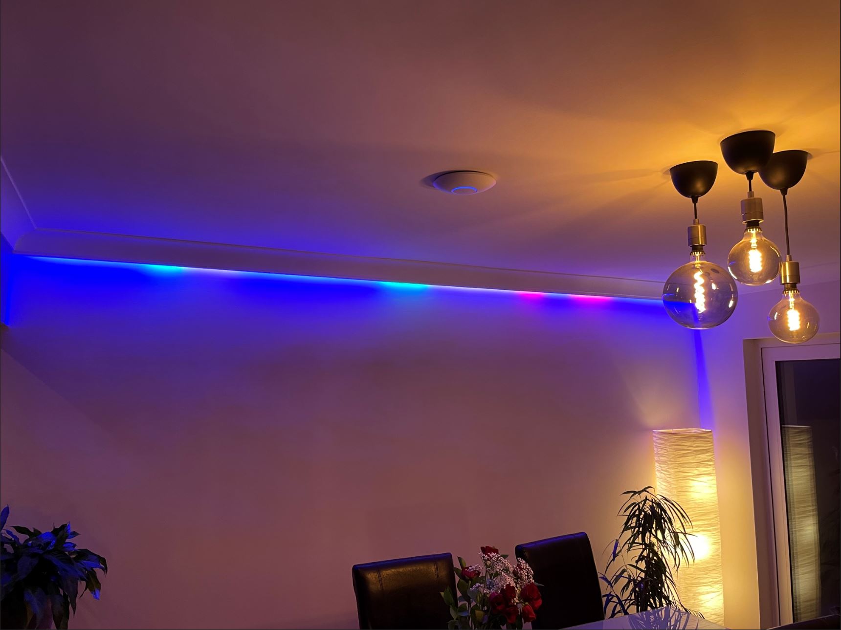
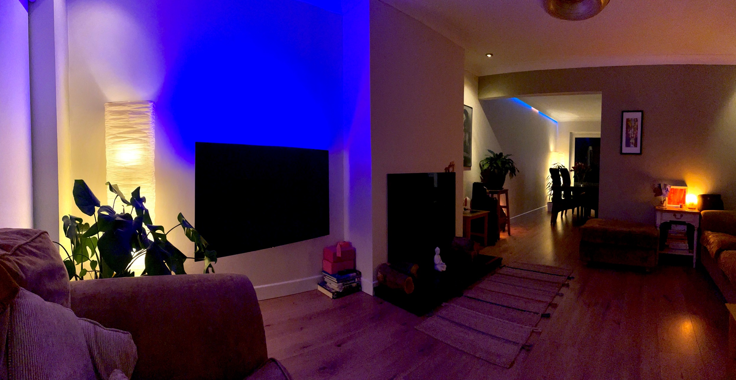
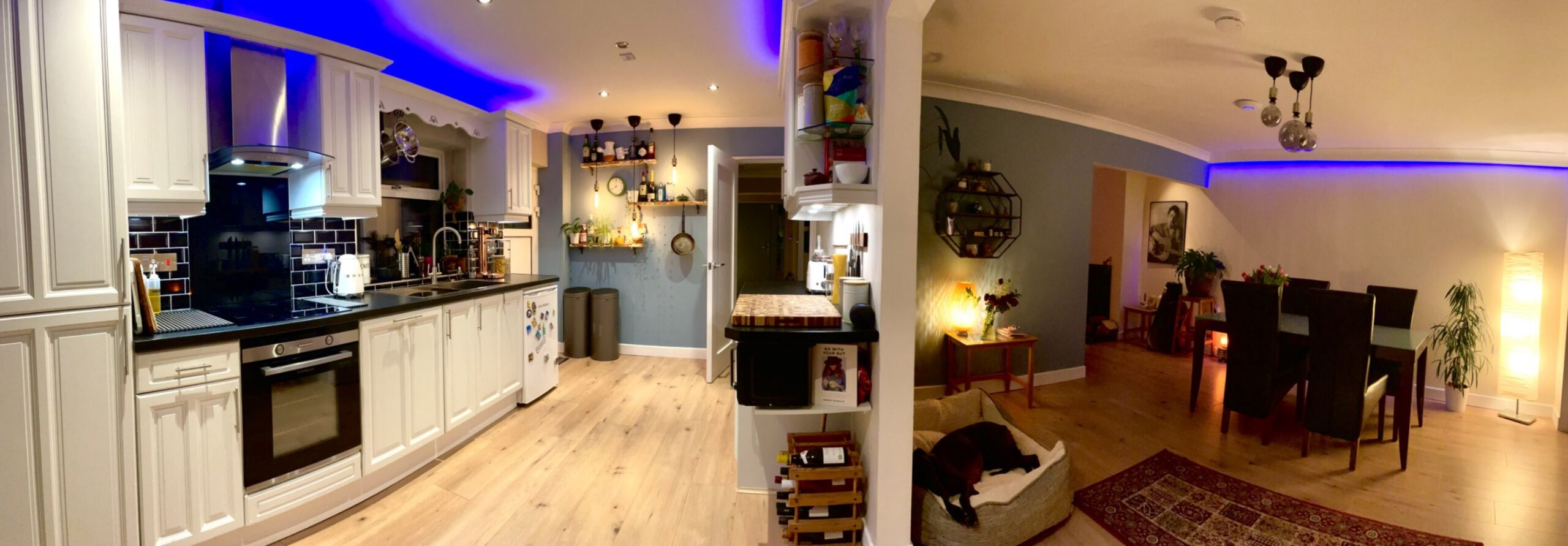
LED Strip Control
I’ll admit at this point, that I did buy a few LIFX wireless LED Strips, despite my aspirations to have a wireless-less system. I had some ideas for hiding them in behind coving, screens/TVs, on top of counters (the usual stuff you see in smart lighting pictures online) and I couldn’t resist the urge. While wiring up the 1.5km of cabling that I added into the house, I have to say, at multiple times I was cursing myself for not going wireless. Whenever I received my LIFX order however, it did provide a feeling of justification for all my extra work. Out of the 5 LED Strips I had ordered, 2 had bad connection issues. One of them was so bad it was completely unusable – only capable of maintaining a connection to the Wi-Fi for a few hours before it loses it and needs a power cycle to connect again. I have a good Wi-Fi network too… I don’t want to hate on LIFX too badly, I fully realise it would make absolutely no commercial sense for them to release this product with wired control – they wouldn’t sell any… well… they’d definitely sell 10 to me… but that wouldn’t be worth their while.
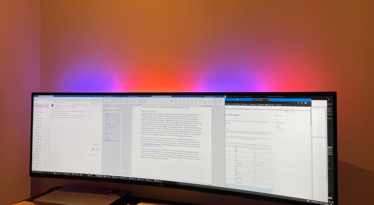
What’s good about them is the LED strips themselves. You can produce incredibly deep, rich saturated colour with these things and they are split up into multiple zones (8 zones per meter), so you can have all sorts of colour mixing and patterns going on. The documentation on their website for how to assemble a LIFX packet is absolutely excellent too. I was up and running, controlling the strips from python within a few hours.
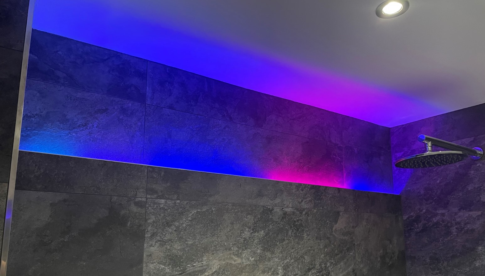
I wanted to have some multi colour effects (see examples below) that could run on the LED Strips. Apple Home, doesn’t really provide the interface for this – its more geared towards setting the whole strip to a solid colour. The way I got around this was by defining a particular combination of Hue and Saturation value that would trigger one of the “themes” from my python script. This special colour setting could be stored in a scene in Apple Home and then used to recall the theme.
Conclusion
This has been a fantastic project to work on, particularly given the timing of it for me. It was great to have something like this to work on during the pandemic, when we all had to stay inside anyway. There are many aspects of the project that I have not been able to touch on as this blog is far too long already.
The main advantage that I have found from taking the DIY approach is that I have ultimate control over everything that goes on. If I don’t like the way something is working in some subtle way, I can alter its behaviour. Any automation I can dream up, with any number of conditions that feed into it is possible. You don’t get that level of control with any off-the-shelf solution. Even though the design and installation was a huge amount of work, now that it’s all up and running, I couldn’t be happier that I decided to undertake this project.
I have all scripts and design files for this project hosted on my github if you are interested in having a look.